


Hello to All. I've seen some other fine examples of ho-made tools along this line, here's my take on it. Not better, just different. At the shop where I work, we've gone thru several hundred inserts boring holes for months on end. My machine alone, about 4500 holes per week. But that's another story. So we've got CCMT (80* diamond, positive rake, 1/4" IC) inserts used on 2 corners only. My aim is to make a turning tool to use the other 2 corners, and while I'm at it, a tool to re-use the first corners. Here's a photo of the plan and the finished tools.
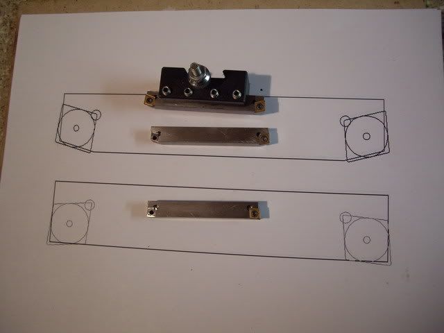
I sketched up the plan on a CAD program, helped me to visualize the RH and LH tools. My plan was to have the 15* lead tools in the QC holder both RH for turning and LH for facing still only one QC holder. Also made a LH and RH tool for the 80* corner.
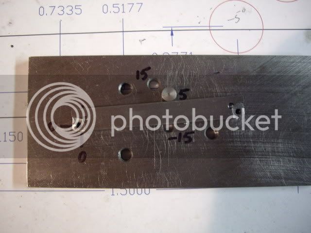
Here's a photo of the fixture I made to mill the pockets. Being positive inserts, the pockets are flat to the holder. There's a pin at X0 , Y0 to locate the parts. The other pin locates the edge of the tool at -15*, -5*,+5*, or +15* to align the different sides of the pockets. I used the CAD program to locate the holes. I used the center of the insert screw as 0,0, so all I need to do was change the angled pins and still mill a 1/8" radius pocket. Then to make the other hand tool, I turned the fixture plate over, to mirror the pockets. The clamps are not on photos for clarity. The holes not labeled are 1/4-20 for the clamps.
Now it's over to my (surrogate) brother's shop, to trade a couple of those tools and inserts for some propane heat and Kasenit case hardening agent. BTW, I chose to use straight sides on the pockets, not 7* as the inserts are molded, I don't see these tools as getting severe use or tool pressure. Again, not better just different, hope somebody can use and / or improve on this info") .
.
Enjoy. DB
I sketched up the plan on a CAD program, helped me to visualize the RH and LH tools. My plan was to have the 15* lead tools in the QC holder both RH for turning and LH for facing still only one QC holder. Also made a LH and RH tool for the 80* corner.
Here's a photo of the fixture I made to mill the pockets. Being positive inserts, the pockets are flat to the holder. There's a pin at X0 , Y0 to locate the parts. The other pin locates the edge of the tool at -15*, -5*,+5*, or +15* to align the different sides of the pockets. I used the CAD program to locate the holes. I used the center of the insert screw as 0,0, so all I need to do was change the angled pins and still mill a 1/8" radius pocket. Then to make the other hand tool, I turned the fixture plate over, to mirror the pockets. The clamps are not on photos for clarity. The holes not labeled are 1/4-20 for the clamps.
Now it's over to my (surrogate) brother's shop, to trade a couple of those tools and inserts for some propane heat and Kasenit case hardening agent. BTW, I chose to use straight sides on the pockets, not 7* as the inserts are molded, I don't see these tools as getting severe use or tool pressure. Again, not better just different, hope somebody can use and / or improve on this info
.Enjoy. DB