A Stuart Turner Triple Expansion Engine

Home Model Engine Machinist Forum

Help Support Home Model Engine Machinist Forum:

This site may earn a commission from merchant affiliate links, including eBay, Amazon, and others.
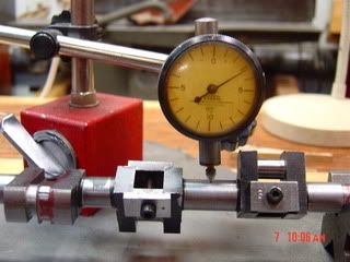
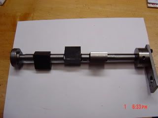
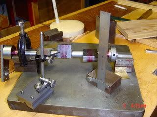
Hillmar, chunks are cut out of the crank blank? doesn't sound good - I think you need the rigidity of the solid bar to start with, turn the pins, put accurately made spacers between each, then turn the journals. more than one way to skin the cat, but that worked for me and I'd not want to try turning the pins with the journal already turned down - too much spring

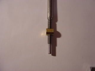
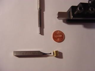
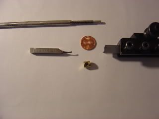
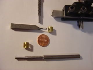
John, its not the 2 start that concerns me, its the 3/16 size. I haven't cut a single point internal thread that small, seems like the tool would be prohibitively spindly, hence the tap idea....we'll see. I've boring bars that small, but the nature of the width of cut with threading would significant increase the force on the cutting tool. ways around that I know, but they might be more of a pita than making a tap. might have to experiment on small dia single point internal threading

I wouldn't need a fourth axis though to thread on the the cnc, three is all you need. I'd still have the same challenge of some very tiny tooling for the internal thread.
 
Hi Mcgyver
Look sorry i just clicked on the sie your dealing with. Dont even bother trying to cut the internal on the lathe the chances of any success are slim to none at 3/16th.
I would go on as follows. Find a bit of 3/16 silver steel twice the length you need and cut your reverser screw screw cut full length so you can make a tap from the same screw cut rod.
Making taps from silver steel is reasonably easy and if done the same time as cutting the reverser screw you should only need to relieve the threads slightly to get a useable threaded assembly.
On silver steel id be inclined to grind a Stelite tool and remove a large amount of the front face to account for the fast helix your cutting. grinding just one flute should be enough but two would be nice for swarf clearing.
go no more than 1 thou cuts to depth.
 
hey it's all good, good info on cutting 2 starts from you and John. I'm not sure cutting the tap and screw at at the same setting will work, screw needs to be slightly smaller than the tap so there's some clearance. I think I'll have go at a tap at major dia., tap, then thread the screw until it fits. The other thing I've found with getting a home made tap to work is to mill away most of the threads leaving a smallish land, otherwise it takes too much torque to turn them

here's a tap that didn't work
http://i20.photobucket.com/albums/b201/michael0100/didntwork.jpg
here's two that did
http://i20.photobucket.com/albums/b201/michael0100/afterheattreating.jpg

main difference is amount of threaded area left. after the first didn't work (couldn't turn it) it was suggest i make the thread area smaller. with 3/16 it'll be a balancing act between minimizing threaded area so it'll turn and not making the core so small its weak. might be braces and a belt, but doing a couple of taps in different %'s of thread depth appeals, ie minimize amount each tap has to take out.....but in making taps this small I'm in uncharted territory, the pics above are 1/2 20 L, at lot easier than 3/16
 
Hi Mcgyver,
I will admit defeat on this one, Kevin seems to have done it a lot more times than me in this small size, and seems a lot more logical to make the male thread at the same time as the tap.
But depending on the material, you just might have to revert to taking a bit of 'meat' out of the female thread to relieve pressure on the tap to prevent breakage, or have a long lead in taper and take it very steady.
It is little problem jobs like this that usually hold up a build for ages, but once done you wonder what all the fuss was about.

John
 
Hi
It does work fine if you think about the thread after finishing you have polished the crests on your screw to remove any burs so its lower than the crests on the tap and vece versa.
If the thread is a little snug work it with BlueBell for a few dozen turns.

cheers kevin
 
Hi, Mcgyver
since you have the planes for the Stuart Triple, I have a question .

The 3/16 x20 T.P.I. as printed on the Plane is

a , 20 T.P.I. cut twice to have 40 threads or

10 T.P.I. cut twice to have 20 threads
I know we talked about the subject but that question was not discussed.

I got different answers from people on that question.
Hilmar

P. S. This new site is real nice here.
 
Hi Hilmar,

i had to look this up, but here's the rule: the lead of a double thread is twice that of a single thread having the same pitch....

from machinery's handbook,

Pitch: The pitch of a thread having uniform spacing is the distance measured parallel
with its axis between corresponding points on adjacent thread forms in the same axial
plane and on the same side of the axis. Pitch is equal to the lead divided by the number of
thread starts.

Lead is the axial distance between two consecutive points of intersection of a helix
by a line parallel to the axis of the cylinder on which it lies, i.e., the axial movement of a
threaded part rotated one turn in its mating thread.


so if tpi= 20, pitch = 1/20 and then again divide by the 2 starts, the Pitch = 1/10

I believe that's saying to cut a 2 start 20tpi thread, its two helix's 180 degrees apart, each at 10 tpi - the gear box is set at 10 tpi but you're only advancing the tool in as per a 20tpi thread.

seems rather daunting cutting a 20 tpi in 3/16 stock doesn't it? and we have to make a tap to boot! you are of course doing this as an acme thread to remain true to full size practice right? (j/j :D)

Hilmar, if you're about to tackle this part, I'll watch with great interest how it works out. these is nothing to stop us from saying, lets have a go at some other number than 20. I'd probably start at 20 and if i couldn't get a decent job of it scale back a bit
 
Hello Mcgyver
??? I am sorry but I forgot to do that thread in ACME, ;D ha ha .
But in any case you do not need a Die or Tap to make the
3/16 X20 TPI.
Have a look at the pix. You will se the finished thread plus two goofs , the one on the bottom.
The internal bit could be a bit heavier . But it worked as is
all thought a bit slow.
You have to take it easy.
the spindel with centre Tail Stock and the nut normal from right to left one 1000s at the time

The lathe I have is a Grizzly 9x20 about five years old.
To cut the second thread I marked the 40 tooth gear on the spindle and moved it buy 20 teeth ( 180° ).I did three spindles and two nuts.
Some one explains to me how to centre the cylindrical nut in the chuck. I used a four jaw chuck but don’t know how close I came wit the centricity..

Hey , Mcgyver if I make an other one I will try the ACME, Ha,Ha,Ha Maybe 20/40
Hilmar

DSC00429.jpg


DSC00425.jpg


DSC00424.jpg


DSC00427.jpg


In the last picture on the bottom you see the two goofs.

How do you resize thos darn Pictures??
 
Hilmar, I am suitably impressed! very nice work,

I will definitely go the single point tool route, I'd convinced myself it was not doable but you've proved otherwise. That has got to be the trickiest looking bit of the project and you did it perfectly to the print, to the front of the class I say.
 
Thanks Mcgyver.

But now I think I need Bogstandard, or Cedge) to Re size the pics. And my question is
what size should they have bin ???? I am using Photo bucket and on there
what should I use for size??
Hilmar
 
Lovely bit of work there Hilmar.
Now you've done it the once, you should have no trouble making all the ones required when everyone rushes out and buys a triple expansion. ;D ;D
Please don't look to me about resizing pictures, I have trouble with my own. There is a post about picture posting.


John
 
I resize pics with paint shop pro myself and set the JPG compression to make them around 70k.

A common web friendly size is 640 wide by 480 tall.

I think I have the software here set so any picture over 800 x 800 is resized to 800 x 800 max automaticaly.

once you upload it to photobucket click the picture, hit the resize button and there will be a 640x480 message board size option.
 
Now that IS some impressive work, both in the finished parts
and the tooling!!

Great job!!!

Rick
 

Now am I the only one who ever bent a triple crankshaft while turning it on the lathe?
Was trying to turn the last Crank. Got too eager, feed the tool to fast, Tool caught on the crank, stalled the lathe and shaft went bang. Shaft bent. In the excitement I forgot to take a pix of the whole process. Worked almost a week on the darn piece. So I put the thing between two V Blocks and straighten it out again. How good we will see later. If it is a no go I have to do it over Of course this never happened to You guys !!!
Hilmar
 
Hi Hilmar, did you get my PM re your question...wasn't sure if it went through and i hadn't heard....if not speak up.

I'll try to snap a pic of the pretzel i made. i wouldn't bother with the silver soldered blank that comes with the kit, its a lot easier to make it from solid imo. let me know if how its going, i think i remember how i did it.

finally got back at mine, minor stuff, drilling out for studs on the valve chest, feels good as i haven't touched it in years (took a multi year hiatus and built tooling)
 
Mcgyver,
Yes,I did send you an E-Mail back .
Then I toughed I could put an attachment to it but that did not work. Have a look in Frequent question I put one there of the item in question.
As for the Crank shaft. It was not silver soldered it was one piece but partially turned and milled. This was my first shaft and then a triple on top of that. It went mostly under size. I could not get the follover in the right place. So I will see how it turned out.
Hilmar

Some more pixs on , machining the crank shaft
DSC00475.jpg

DSC00515.jpg

DSC00505.jpg

DSC00510.jpg

DSC00499.jpg

DSC00486.jpg

DSC00490.jpg

 
That is a neat way to turn the crank between centers! I might have to try that.

Thanks for the pictures, Wes
 
This is what I have so fare.

DSC00900.jpg

In the winter the shop was kind of cold, so not much got done in there.
Some of you did followed the tread in >Cast Iron< know that things went wrong some where. I think it is the Edge Finder off Set. Murphy must have bin hanging around my shop.
The LP + IP casting is off by around 0.100 ". That means the Crankshaft is not lining up with the center of the cylinders.
I have to look now for alternatives. Scrap the Cylinder and make a new one, make a new Base, buy a new Cylinder and Base ( since I don' know if I buy only one part that it will fit on the old part, there are 40+ Years different. So I got to think (I should have that done before) to what to do.
In the mean time I may make some more parts .For fit I will put the head on the columns and see what will happen.

Here is the Lap I used for lapping the LP Cylinder
DSC00896.jpg

DSC00893.jpg

Copper clad Cherry Wood
 
looking good Hilmar, a couple of eccentrics and you're done!

so as you're getting close to the final straightaway, have your thoughts turned to what kind of great boiler you're going to make.........expansion engines really don't won't to work on air...
 
Cant bore it oversize and sleeve it then rebore in correct position?..Shame to have to start all over...Looks too good to quit on..
.
.


Latest posts

Back
Top