


Richard Horne
Member
- Joined
- Dec 4, 2008
- Messages
- 15
- Reaction score
- 12
A Stirling Experience
Ive always been fascinated by desktop Stirling engine models. In particular, I admire the high temperature models that run from the heat of a flame. They are robust enough to be called real engines and are mechanically beautiful when carefully finished and outfitted.
However, my shop and my abilities are modest. I have only a 9-inch lathe and mini-mill with no computer controlled machinery for production of complex parts. I had also been reluctant to try Stirling engine models because of their reputation as needing the highest precision work. There several tales of woe on the Internet hobby sites related to building Stirling engines.
However, once I had gained some experience by completing two steam models, it was time to take the plunge and find plans for a Stirling engine model that I could conceivably build. After a good deal of searching, I settled on the Stirling BAS model designed by Jan Ridders of the Netherlands. This beautiful engine is about 200 mm (7.9) in length and has a 100mm (3.9) flywheel. It is made mainly of aluminum and brass, and it uses Pyrex glass test tubes for the cold cylinder, displacer, and power cylinder. It uses miniature ball bearings for all rotating joints in order to minimize friction and will run merrily along at 300 rpm or more using the heat from a small tea candle as the power source.
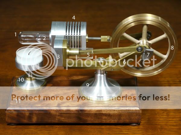
1 Hot Cylinder
2 Displacer (internal)
3 Mounting Block
4 Cold Cylinder
5 Power Cylinder
6 - Fork
7 - Crank and Web
8 - Flywheel
9 - Central Engine Support
10 - Candle Holder
11 - Wooden Base
I completed this engine with about 400 hours of work and many highs and lows along the way. In the following paragraphs I will give a summary of the most challenging episodes with the wish that others will try building this beautiful engine.
You can obtain the complete plans for this engine from Jan Ridders web site. Please be sure to leave a small donation for these excellent plans.
Metric versus inch
For those who ordinarily work in inches, it is still fairly easy to match the metric dimensions of the plans when building this model. You will divide millimeters by 25.4 a thousand times, but the conversion quickly becomes automatic. However, the metric sized screws, along with their associated taps and dies, may be difficult or expensive to obtain in the United States. My solution was to use American Standard UNC thread screws that closely approximate the specified metric sizes.
Test Tubes and O-Rings
This engine uses Pyrex glass test tubes for the hot cylinder, the displacer plunger, and the power cylinder. The hot cylinder and power cylinder are sealed within the mounting block with rubber O-rings. The first obstacle is that you will never find Pyrex test tubes with exactly the inside and outside diameters specified in the plans. Many different Pyrex test tubes can be found for sale on the Internet, but it is impossible to tell exactly what their inside and outside diameters are without having a tube in hand. My solution was to purchase samples of half a dozen different sizes and pick those that were the closest match to the plans. Rubber O-rings can then be ordered to match the chosen outside diameters of the hot cylinder and the power cylinder. Of course you will have to adjust the plans for the mounting block to take into account the actual diameters of the test tubes that you have chosen.
You must also learn to cut the Pyrex test tubes to the required length. I tried procedures found on the Internet including scoring and breaking, and heat shock with the red-hot tip of a glass rod after scoring. I also purchased a commercial tube cutter advertised to be very accurate. All of these techniques worked once in a while, but I was never successful more than about 20% of the time. So be prepared to break a lot of test tubes. I have seen others on the Internet that use a small abrasive disk to make these cuts, so perhaps this procedure will be more reliable for those having the equipment.
The Mounting Block
The mounting block, which holds the hot cylinder, cold cylinder and power cylinder, is the heart of the engine design. It has a complex shape machined from 12mm thick aluminum. Such a combination of arcs and flat surfaces would best be machined with a computer-controlled mill. However, I needed a way to make this part without recourse to computer-controlled machinery.
If I had tried to make this part by hand filing down from a rough-cut shape, the result would have been unsatisfactory. It would never have had the crisp, finely finished look that the engine deserves. Instead, I divided the block into four separate parts that could each be machined using only a lathe and mini-mill. These parts were then bonded together with internal pins held in place with Locktite 680 retaining compound. The internal bore connecting the cold cylinder and power cylinder was lined with a continuous brass tube for air tightness.
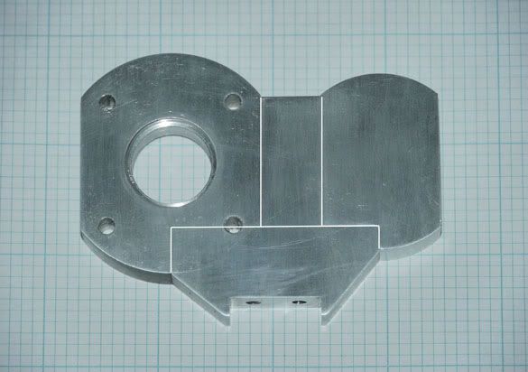
With careful attention to detail, the mounting block can be accurately built from separate pieces bonded together. Others may have the skill to hand file the entire shape, but this was beyond my ability.
One word of advice regarding use of retaining compound is that the stuff sets up within just a few seconds when confined in a tight joint without oxygen. You wont have time to fiddle with parts while assembling them. Be prepared to press the parts together accurately the first time without the need for fine adjustment.
The Fork
The mounting block sits on a strip that extends horizontally and holds upright bearing supports for the flywheel, forming a fork. Purchase the flywheel ball bearings before building the fork. Then you can be sure that the bearing holes in each support are the correct diameter for the available bearings.
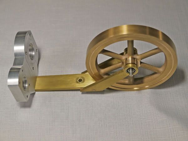
The upright bearing supports are pinned and soldered to each side of the supporting strip to form the fork. The alignment of this fork is vitally important. The flywheel bearings must be held at the correct distance and height from the base of the mounting block, and they must be aligned horizontally with no measurable tilt. This requirement calls for a very precise alignment jig designed to hold the bearing supports accurately in place while they are soldered. Building this jig deserves considerable attention since it will determine the ultimate alignment accuracy of pistons, cranks, and the flywheel.
My solution was to build a precise right-angle jig with a support plate and vertical spacer bar of the exact width needed between the bearing supports. This spacer was then drilled at precisely the height of the flywheel bearings. The fork assembly was then positioned on this jig with accurately placed pins and with a simulated flywheel axel. Cutouts were made in the jig to allow for soldering and to prevent any overflow from soldering the fork to the jig itself.
Flywheel and Cranks
I could never have built the flywheel shown in the plans without the use of a computer-controlled mill for machining of the interior spokes. The plans call for a 100mm diameter flywheel. As an alternative, I purchased a fine cast bronze flywheel of 98mm diameter from AtelierMB on the Internet. The hub was machined to the dimensions specified in the engine plans.
The two steel cranks and crank webs, one on either side of the flywheel, are standard in design but will require some ingenuity in set up to mill the pie-shaped counterweights. With careful attention, you should have no problem with these. However, I do recommend a change to the plans here, which call for a 13mm deep tapped hole for a setscrew on each crank web. With my US thread conversion, this results in a 4-40 thread setscrew in a ½ inch deep threaded hole. With my humble ability, there is absolutely no way to tap a 4-40 thread clear through a ½ in thickness of steel. The tap will always break about ¾ of the way through, ruining the piece. My solution was to drill out the hole at the setscrew diameter, leaving a depth to be threaded of about 1/8 inch. This gives five thread turns for the setscrew, which is more than adequate in this case.
Central Engine Support
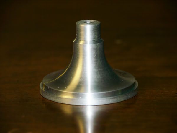
The central engine support as designed has a beautiful curve that sweeps up from the base to the neck that supports the mounting block and fork. The curve is actually an arc of 20mm radius. Again, a computer-controlled lathe would have been useful here. Instead, I decided to create this precise arc by hand.
Using a spreadsheet program on a personal computer, I created a table giving depth of cut for the lathe in a series of 40 steps, each 0.020 wide along the rotational axis of the part. I then manually made these 40 cuts, creating a stepwise approximation of the arc. It was then easy to smooth the curve using a fine file and emery paper.
Displacer, Cold Cylinder, Power Piston, and Driving Rods
Making each of these parts based on the plans is straightforward though labor intensive. I used brass for the power piston rather than graphite. The plans indicate that brass is acceptable here, and I didnt want to deal with the mess created when machining graphite. Extraordinary care is needed for precise fit of the pistons and piston rods, as you will see later.
Candle Holder
The candleholder will give you no problems. I do recommend that you purchase a box of tea candles in advance so that you can size the candleholder cup to precisely fit the diameter of the available tea candles. I had to build a second cup when I found that my tea candles were smaller than expected and prone to rattling around in the cup.
Base
Although not absolutely necessary, Jan Ridders design for a wooden base is simple and elegant and does much to enhance the beauty of the model. I suggest obtaining a nice plank of hardwood with an interesting grain pattern and finishing off the model with a polished wooden base. I used a router bit in my mini-mill to cut the sides and contoured edge of the wooden base.
Final Assembly and Test
Ah, the moment of truth. After hundreds of hours of work, all the parts are finished and it is time to assemble the engine, hold ones breath, and light the fire. Be prepared for a letdown. In every project there must come a point where one asks, Why did I ever think I could make this work? This was such a point for me. I could spin the flywheel, but the engine would not continue running for long even with the candle cranked up high against the hot cylinder. After a day of fumbling with it, I went to bed in a terrible mood.
With the morning light I reconsidered what could be done to salvage the project. The most obvious thing to do was to attack possible sources of pressure leaks. So to do this, I rebuilt the displacer rod and its bushing where it exits the cold cylinder. My normal practice for slip-fit bushings is to ream the bushing to a diameter 1/1000 larger than the rod. This usually gives a tight, smoothly running fit, but apparently this wasnt good enough here. My solution was to ream the bushing to a diameter 1/1000 SMALLER than the rod. Then I mounted the rod in the lathe chuck, and turning it at high speed, slowly ground it down with fine emery paper held in my fingers. It only took a few swipes before the rod fit smoothly into the bushing. I should also mention that I used a 3/16 inch diameter (4.8mm) rod rather than the 4mm specified in the plans. This allowed me to use standard 1/1000 over and under diameter reamers in making the bushing.
I also rebuilt the power piston to fit more tightly in its glass cylinder. I could feel the creation of a slight vacuum when the power piston was moved, but I suspected that the effect should be greater. One wrinkle you will encounter here is that the inside diameter of the glass test tube varies slightly over its length. My guess is that this variation is no more than .0005, but this is enough to cause binding in spots when you are being so meticulous in finishing the piston diameter. As before, I ground the piston mounted in the lathe chuck using fine emery paper held in my fingers until I just achieved a smooth motion through the entire length of the glass cylinder.
One other note the plans suggest using silicone as a sealant at each end of the cooling fin section of the cold cylinder, but I did not find this necessary. Perhaps dumb luck was responsible, since Ive read that others building the engine did find the silicone to be necessary. My recommendation is to avoid the silicone if you can. It is such a mess to remove if you ever need to disassemble the engine.
Once the rework was complete, the engine was reassembled and ran immediately. Happiness is a running engine!
[ame=http://www.youtube.com/watch?v=zMs9MLWpeb8]http://www.youtube.com/watch?v=zMs9MLWpeb8[/ame]
Notes on Running
The plans advise using no oil on any of the moving parts. In fact, the plans recommend removing any trace of oil from the ball bearings using naphtha solvent. The viscosity of the oil is said to actually inhibit smooth running of the engine. I do run the ball bearings dry as recommended. However, I did add a tiny drop of mineral oil to the displacer rod at the cold cylinder bushing. This is a point of wear and the tolerances are so tight that this step seems prudent to me. I saw no change in engine speed with this lubrication.
You need as large a candle flame as possible. The candle flame will be puny and not adequate to run the engine if the wick is broken off to a nub. Either dig out the wick or substitute a new candle if necessary.
The highest setting of the candleholder will be with the tip of the flame just below, but not touching, the glass of the hot cylinder. If you allow the flame to touch the glass, soot will immediately develop. This soot is really awful stuff and is to be avoided. It is a microscopically fine carbon powder that stains anything it touches. It cannot be removed from clothing or tablecloths (as my wife can attest). It can be easily removed from the glass cylinder with a dry paper tissue. But dont let this tissue then touch anything else that you prefer not to have stained with an indelible black smudge.
Conclusion
Building Jan Ridders Stirling BAS engine is very challenging and enjoyable. It will test the skills of an intermediate level modeler using basic lathe and small milling machine. The final result is impressive as a showpiece and most fascinating to run. I will be happy to hear from any others struggling along the way. Post comments to this forum or send email to [email protected].
Richard Horne - May 2011
")