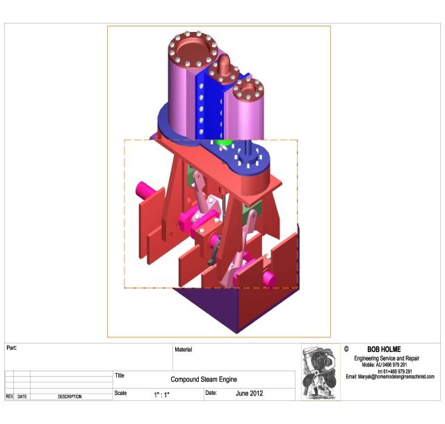
Ok, here is my slant #2 on the "mystery compound" as I hereby dub this engine.
Picture a twin cylinder compound vertical engine with crank pins 180 degrees apart.
So when one piston moves up, the other moves down.
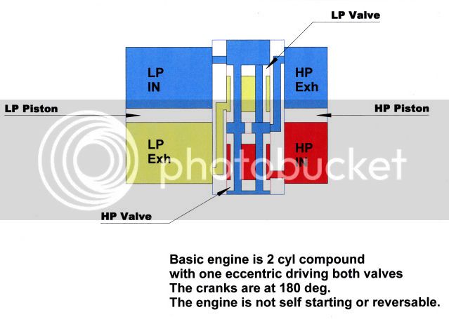
Now use two standard piston valves between the cylinders, and mount the valve stems to a common yoke that is operated from one eccentric only.
The valve on the right is inside admission.
The valve on the left can also I think be inside admission, and you need passages from the outside of the right valve to the inside of the left valve.
Since the pistons act opposite each other, then valve action can be mirrored (sort of), and operated off of one eccentric. If the engine did not have crank pins at 180 degrees, then you would need two eccentrics to time the valves correctly.
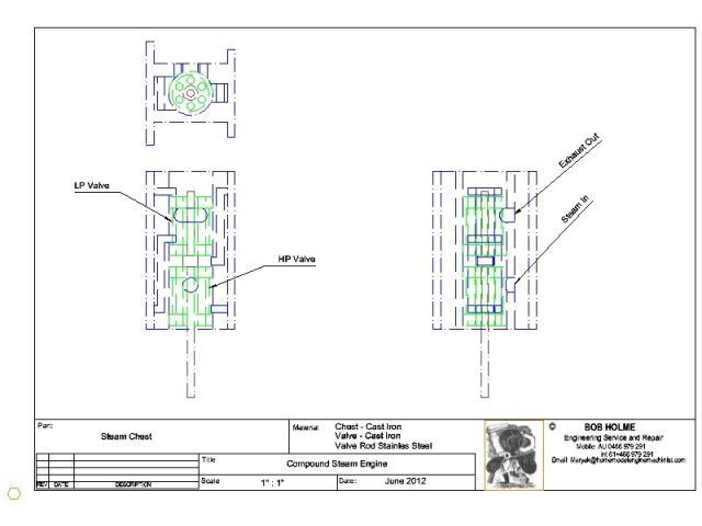
So in order to get the arrangement that Bob has above, stack the two piston valves in a common sleeve, make them into a single valve, and allow exhaust to run inside of it in a hollow space inside the thimble.
That is going to be a long valve, and the only way to change the timing is to make a new valve.
Makes for some unequal passage lengths, but certainly would be a functional engine.
That's my guess. (Wow, I am only 7.5 hrs behind steamer dave. Pretty good in my book, if I am right that is.)


")