


- Joined
- Jan 17, 2009
- Messages
- 887
- Reaction score
- 81
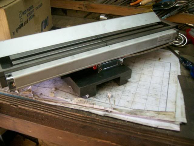
Look what came through my door this morning:
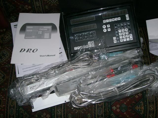
I ordered it from this firm.
http://www.machine-dro.co.uk/
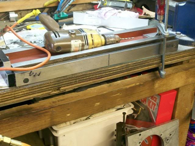
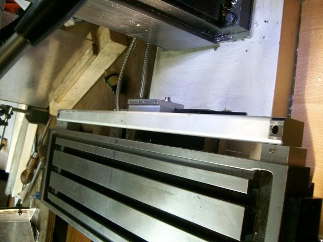
Start of the job was to strip the mill down and work out best way to fit the scales.
You need to find the centre of travel of your mill to mount the scale.
Mark the two extremities onto the knee of the mill
Half way between these marks is the half way point to mount the centre of your scale
Extend the mark over the table to where the scale is to mounted. I removed the x, y tables so I could see what I was doing.
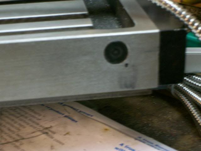
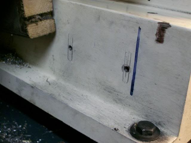
Wouldn't you know one of the holes will end up close to the coolant drain hole :scratch:
Before I started drilling holes into my beloved mill I consulted Bogs and he gave me some good pointers.
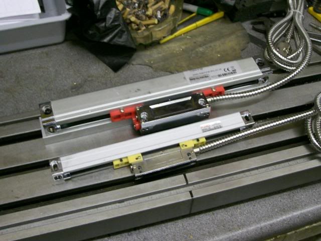
One thing that he did point out was I was using what they call standard glass scales, which are quite a bit thicker that the slim line type that you can get these would have made the job easyer, but they cost more.
To avoid coolant drain hole, I positioned the hole 20mm away and will use a spacer to regain position.
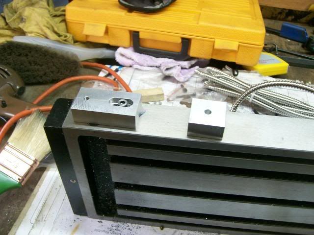
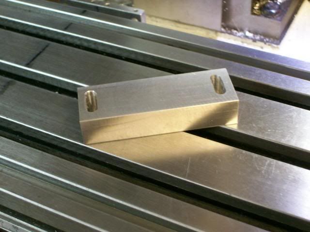
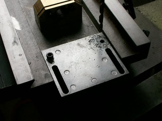
These are the spacers they were made from the same block of ally, so they will be the same thickness, the smaller spacer on the right is for the other end of the table.
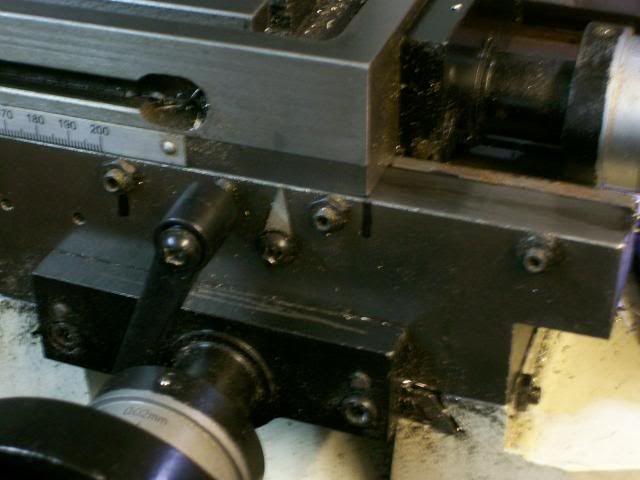
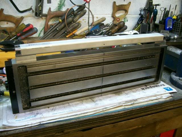
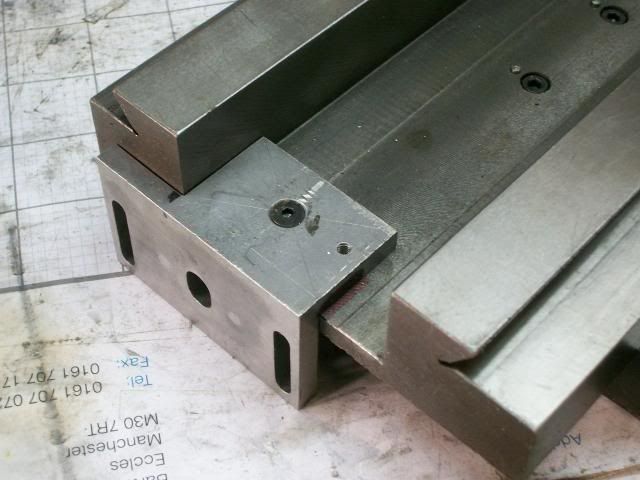
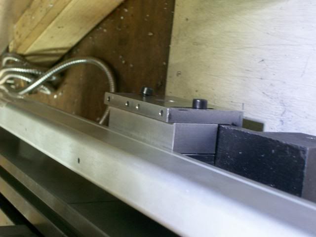
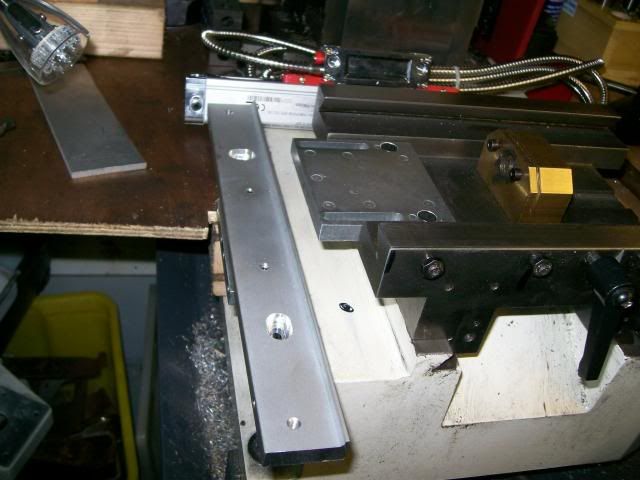
This is how they fit
The reader I mounted on an angle bracket mounted on the underside of the slide.
A spacer was required between this angle bracket and the reader, as it was awkward to get in I measured the distance with a pair of callipers measures the callipers and made the spacer to that thickness.
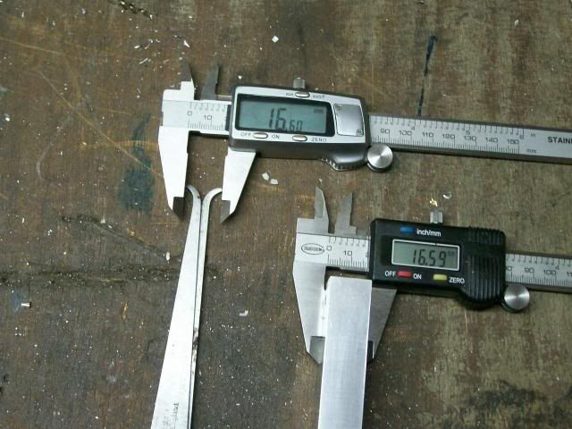
A couple of slotted holes completed the spacer.
Her it is in place
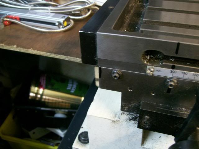
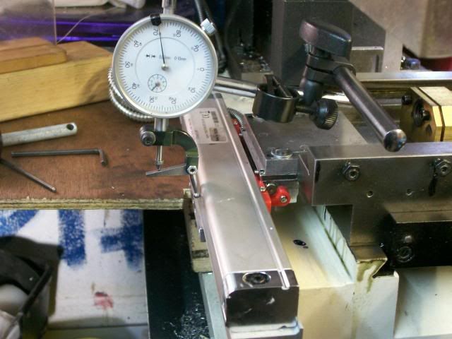
The glass scale was leveled up.
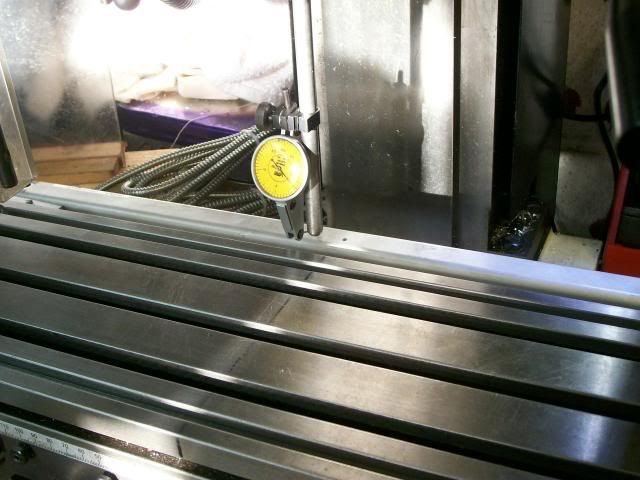
Thats it in place
Thats the Y axis done.
For the X axis two hole were drilled and tapped M5 in the machine base.
And a angle bracket to take the glass scale fastened to the machine, the upper two cap screws are for jacking the bracket level, I used the digi level to get things near.
To mount the the reader a slotted plate was fixed to the slide with M5 cap screws.
These are the two brackets in place to fix the scales and reader.
The scales were leveled up.
And thats it Job done
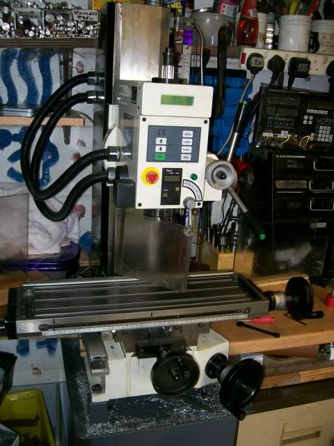
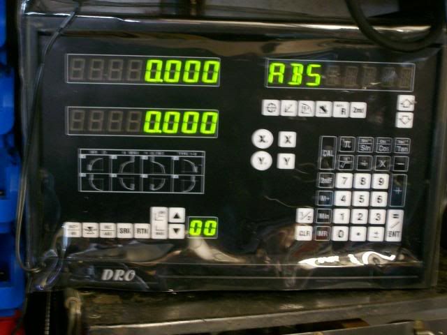
Plugged in
Once I got over my fear of drilling into the machine it was all quite straight forward.
Have fun
Stew
I ordered it from this firm.
http://www.machine-dro.co.uk/
Start of the job was to strip the mill down and work out best way to fit the scales.
You need to find the centre of travel of your mill to mount the scale.
Mark the two extremities onto the knee of the mill
Half way between these marks is the half way point to mount the centre of your scale
Extend the mark over the table to where the scale is to mounted. I removed the x, y tables so I could see what I was doing.
Wouldn't you know one of the holes will end up close to the coolant drain hole :scratch:
Before I started drilling holes into my beloved mill I consulted Bogs and he gave me some good pointers.
One thing that he did point out was I was using what they call standard glass scales, which are quite a bit thicker that the slim line type that you can get these would have made the job easyer, but they cost more.
To avoid coolant drain hole, I positioned the hole 20mm away and will use a spacer to regain position.
These are the spacers they were made from the same block of ally, so they will be the same thickness, the smaller spacer on the right is for the other end of the table.
This is how they fit
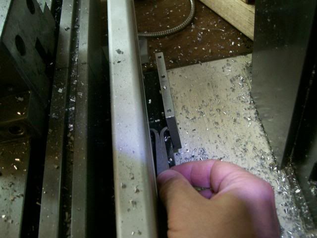
The reader I mounted on an angle bracket mounted on the underside of the slide.
A spacer was required between this angle bracket and the reader, as it was awkward to get in I measured the distance with a pair of callipers measures the callipers and made the spacer to that thickness.
A couple of slotted holes completed the spacer.
Her it is in place
The glass scale was leveled up.
Thats it in place
Thats the Y axis done.
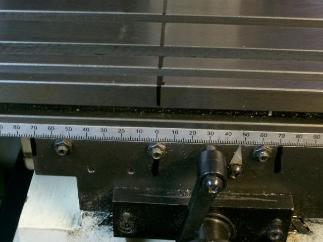
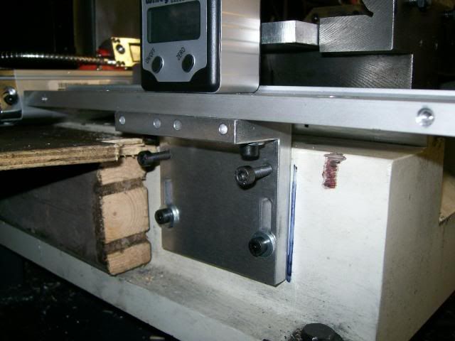
For the X axis two hole were drilled and tapped M5 in the machine base.
And a angle bracket to take the glass scale fastened to the machine, the upper two cap screws are for jacking the bracket level, I used the digi level to get things near.
To mount the the reader a slotted plate was fixed to the slide with M5 cap screws.
These are the two brackets in place to fix the scales and reader.
The scales were leveled up.
And thats it Job done
Plugged in
Once I got over my fear of drilling into the machine it was all quite straight forward.
Have fun
Stew