gantry crane mobile homemade built yourself

Home Model Engine Machinist Forum

Help Support Home Model Engine Machinist Forum:

This site may earn a commission from merchant affiliate links, including eBay, Amazon, and others.

babolottino

Well-Known Member
Joined
Jul 18, 2014
Messages
64
Reaction score
1
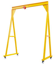
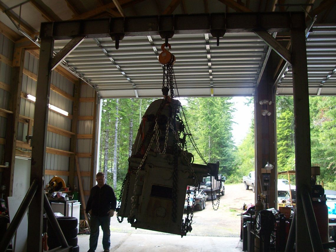
hello I realize a hoist gantry Mobile measurements: width = 10 feet, 10 feet under hook height, width, base of support pillars 7 feet 2 tons capacity in steel beams. I should accomplish in steel beams, the cross section of the ipe 200mm vertical pillars hea 120 or boxed steel pipe 100x100 mmsaldati the gussett and reinforcements plates and bolts to size them I could help you fotondisegni or calculations from which I can draw inspiration or examples thanks to those who will want to help me

workshop-gantry-cranes-8165-2327039.jpg

images

grues-portiques-legeres-14275-5896835.jpg
 
100_3561.jpg


Here is the crane I designed and built. It stands just under 14 feet tall. In this picture it is point-loaded with one of my milling machines, weighing almost 8000 pounds.
 
I had one at work very similar to the one in the last picture on your post, except we had a fixed 2 ton block and tackle. It worked very well, we made it out of "H" section steel.

Paul.
 
Just something I designed and yet to build.
Has the capability to adjust height from 2 meters to just over 3 meters.
The top beam is clamped in so you can either adjust width or put a bigger beam in if needed.
Will build this one day.

03.jpg


01.jpg


02.jpg
 
Agreed, 2"-3" x 1/4" strip between the caster mounting plates would be in the right area, it'll be in tension so doesn't need to be box-section, otherwise the welds on the.legs are going to be under a serious "peeling" load and would be first to fail in service...

If the.top beam's clamped, rather than welded, you won't have much torsional stiffness either, it could be wise to extend the top beam beyond the uprights and brace (triangulate) the top corners, just in the.interests of safety - a swinging load could easily collapse the lot otherwise!
 
Hey Paul and Dave.

There is already a brace for the legs and it is 100 x 8.

I also believe that with the clamps as they are, they would offer more than enough torsional strength and as there is a trolley that if you did try and lift something at an angle ( which you shouldn't do anyway ) then the trolley would simply move vertical and so stop any swing.

Cheers.

04.jpg


05.jpg
 
thank you friends users lighthouse treasure your advice, as the beam size epilastri we have to size the gussett and perforated plates and the diameter of coupling bolts reinforcements and the wheels thanks again sorry if I take this opportunity to the next
Location-de-portique-de-levage-de-2-t-en-Isere-859.jpg

portique-datelier-f500-kg.jpg

6125.jpg
 
Hi.again Ausdier,
Agreed there's a brace, but by positioning it there near the top you'll apply probably 4 times as much tension to.it, and more importantly 4 times the force to the welds... A bigger triangle is always less stressed :)

How low friction is your trolley? Anything less than frictionless and it WILL apply a load along the beam if you apply the lift at all off vertical, and any swinging of the load will do its best to 'lozenge' the structure, once there's a displacement of the beam relative to the support points it WILL collapse, this is why commercial gantry cranes (unless massively over-built) ALWAYS have some sort of diagonal bracing at the.top corners!

A simple application of moments around the top Corner should illustrate the forces applied.to the clamp you drew up, there's quite a bit of leverage applied to it if the load is off square - you could model it with 'scaled' components and loads I suppose, and see how easily it collapses? For the full size I'd recommend proof testing with a 2x or 3x safe.load JUST off the ground ( something you don't mind dropping, a pallet.of sandbags perhaps) and giving the load.a hefty shove.along the line.of the beam, then standing back...

Just my safety-conscious ha'pennorth!
 
file.php

hello friends forum users, now with a bit of calm I started to design the plates would be 4 coupling plates and fixing 2 be fixed at the head of the pillars pillars, 2 to be fixed at the ends of the horizontal cross beam, empirically not mathematically as I have not found reference formulas I sized plates with these dimensions: length L = 700 mm; width l = 200 mm, thickness s: 10 mm holes for plate No. 15, m20 bolt diameter by 35 mm long, it is only if you have a design hypothesis errors to report me, I invite you to do so, please attach photos or drawings or mathematical formulas a + immaggine worth a thousand words thanks again for the collaboration to the next0

portique.jpg

Portique-de-levage.jpg


images


file.php

file.php

file.php
[/IMG]

portale.jpg


crane.jpg
 

Latest posts

Back
Top