arnoldb
Well-Known Member
- Joined
- Apr 8, 2009
- Messages
- 1,792
- Reaction score
- 12
I've hinted in a couple of posts that I'm busy on some design work of my own.
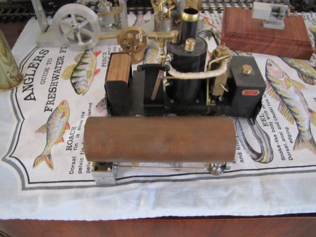
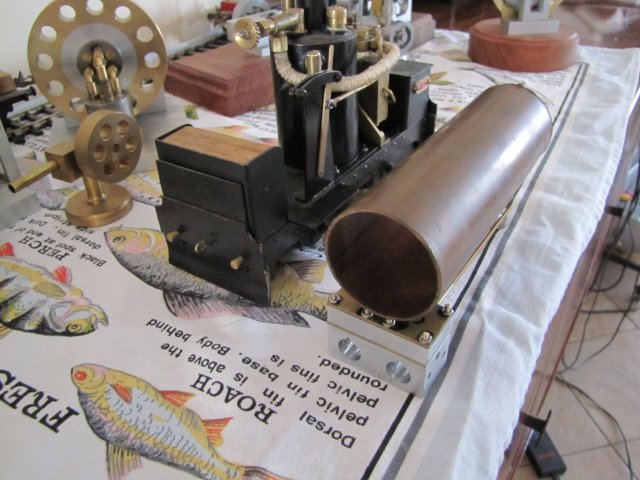
My long-term goal is an O gauge 060 locomotive with functional tender that's fairly easy and cheap to build and a good no-nonsense runner. I've learned many valuable lessons from building and running little Fred, and while I love the little loco, it has quite a couple of flaws - which I'm not going to attempt to correct, as I like the loco as it is - it carries many fond memories!
While working on my design, I've gained a VERY healthy respect for designers who draw up a model and then proceed to build it - it is a huge challenge!
So far I have spent a lot of time on research - from pointed questions asked in the Boilers section on HMEM to reading and fully trying to understand each bit of information I could lay my hands on relating to boiler design, how steam works in small models, and studying different valve gears to figure out how they work.
I'm slow with CAD - which makes matters worse, so I've resorted to just hand-drawing parts when I've had a bit of inspiration. And material selection is a bit of a problem; I have to work with what I have available. O gauge is fairly small, bringing some additional challenges...
I've reached a point where it would be easier to actually make some bits than try and run them through my mind. Thus, this thread will not be along the lines of a quick and deliberate build to established plans, but a changing work most likely with a LOT of failed bits and re-designs to reach an end goal. I'll share all the trials and tribulations along the way; maybe there would be some useful information for someone in there. And if anything's good for a chuckle, that's also fine by me - building boo-boos is more fun than no machining at all")
Experimentation first - I need to see if the idea I have for valve gear will work. First prize would be full Walschaerts gear - but I have a simplified valve gear in reserve... For a start I need the basics of an engine - a working cylinder, a way to mount it, simulate a loco drive train and then "play" with the valve gear.
First up, a cylinder along the lines I have in mind - outside admission D-Valve, 10mm bore, 14mm stroke, 5mm thick piston - a rough C-o-C of the plan, and a block of aluminium to make it from:
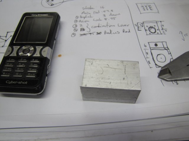
The block's a bit big; it's 1" square stock about 43mm long. My design calls for a cylinder block 20mm long, 16mm high and 18mm wide. So I milled it down to 20mm in thickness first:
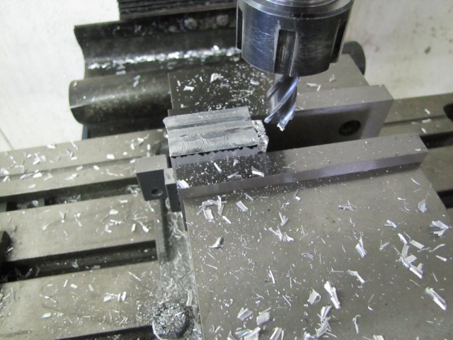
Really hogged it to 20.5 mm hence the big chips, then took the last 0.5mm off slowly to get a better surface finish.
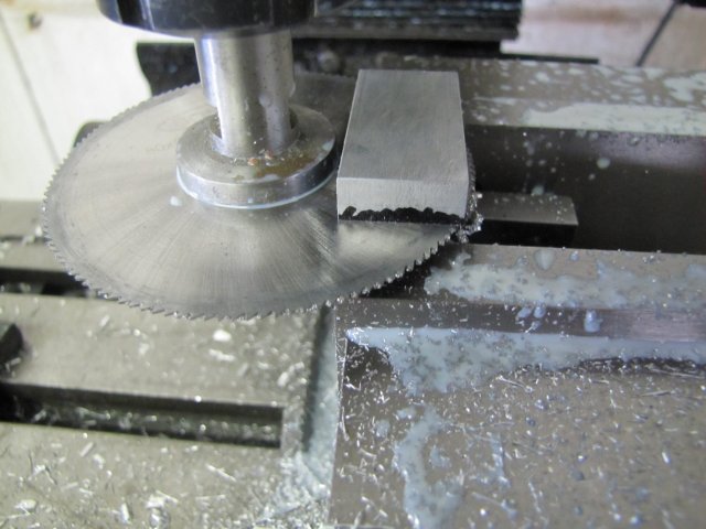
As the block had more than enough material left on it to also make the steam chest from, I slit off the top to make the steam chest from and leave the block 16mm high, rather than waste all that aluminium by turning it into chips:
At this point one of the realities of my endeavour kicked in; this cylinder would be quite small... Not nearly as small as Elmer's Tiny, but still, it would present some workholding issues. In fact, there was enough material on that aluminium block to make two cylinders from - while making machining easier..., So I started making two cylinders from it. I marked it out for two, then drilled the first cylinder; a 6mm through hole (just convenient to fit the mill's collet chuck), then 9.8mm, and finally reamed it to 10mm. The reamer is actually a hand reamer that I chucked in the mill - slowest speed and lots of methylated spirits which I use for cutting fluid on aluminium, and it makes for quite a presentable bore:
The cylinder bore on the right-hand side received the same treatment
With two cylinders-in-making needing port holes drilled, it just seemed logical to have a think around what's needed in terms of valve chests, valve plates and covers. Cue some small bits of 1mm thick brass:
I couldn't be bothered to set up to mill the plates to size, so a quick bit of filing was in order. Good for some exercise to work off the effects of Christmas and New Year:
I thought I'd be clever and stick the bits together with some cheap CA glue (Superglue/Crazy Glue):
I did say CHEAP CA glue; it didn't work, and while drilling the first 1.6mm bolt hole, it started coming apart, so I fell back to some of my "friends" for keeping things together; the much underestimated toolmaker's clamp:
The bolt hole is 1.6mm for threading M2 - most of the holes will need drilling out to 2mm clearance later on.
While the going was good, I kept the valve plate fixed to the cylinder block, and laid out one side of the valve holes:
The other side was done simply; clamp up on the side that was done, and remove the clamp on the side to do. Have I mentioned how convenient the height gauge is for jobs like this ? - I can't believe I took so long to make one!
Some drilling in the mill followed. I didn't bother to center punch any of the holes (In fact, I've stopped center punching any hole spots for the last couple of my builds!) I just located the first (top left hand) drilling position as accurately as I could, zeroed, the dials on the mill, and co-ordinate drilled the rest off readings of the handwheels - keeping backlash in mind:
The center drill I used (actually a spotting drill followed by a normal drill would be better - but I don't have spotting drills) has a convenient 1mm tip - but it does make a larger hole - it ends up at about 1.1mm - but OK for the valve plate and spotting through to the engine block.
Some milling followed. Seeing as I'd done things by setting the mill dials, this was quite easy. My smallest milling slot cutter is 1.5mm - this is bigger than the 1mm holes I need. By using the valve plate with pretty near correct sized holes, I could slightly offset the bigger cutter to mill the steam and exhaust ports in the block. The steam ports are offset 0.25mm to the outsides, and the exhaust port smack bang in the middle. This leaves a 0.75mm wall between steam ports and exhaust on the block; a bit tight, but it should do:
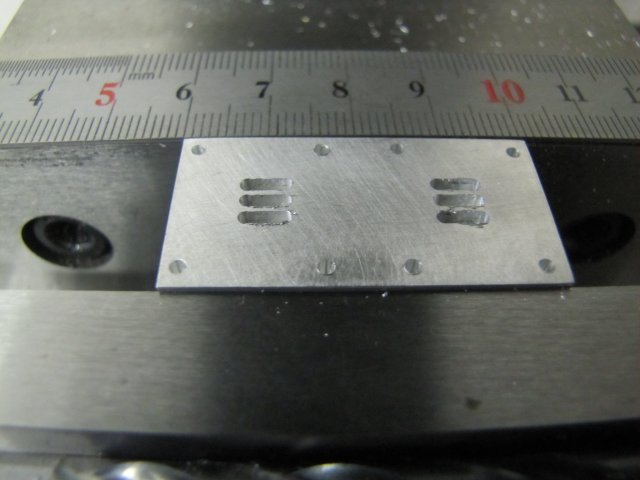
The ports look a bit crappy in the photo, as there's a lot of burrs. Some flat-lapping removed those, and things are looking up
That was it for today's work; not a lot to show, but some chips to start off the new year ;D:
Regards, Arnold
My long-term goal is an O gauge 060 locomotive with functional tender that's fairly easy and cheap to build and a good no-nonsense runner. I've learned many valuable lessons from building and running little Fred, and while I love the little loco, it has quite a couple of flaws - which I'm not going to attempt to correct, as I like the loco as it is - it carries many fond memories!
While working on my design, I've gained a VERY healthy respect for designers who draw up a model and then proceed to build it - it is a huge challenge!
So far I have spent a lot of time on research - from pointed questions asked in the Boilers section on HMEM to reading and fully trying to understand each bit of information I could lay my hands on relating to boiler design, how steam works in small models, and studying different valve gears to figure out how they work.
I'm slow with CAD - which makes matters worse, so I've resorted to just hand-drawing parts when I've had a bit of inspiration. And material selection is a bit of a problem; I have to work with what I have available. O gauge is fairly small, bringing some additional challenges...
I've reached a point where it would be easier to actually make some bits than try and run them through my mind. Thus, this thread will not be along the lines of a quick and deliberate build to established plans, but a changing work most likely with a LOT of failed bits and re-designs to reach an end goal. I'll share all the trials and tribulations along the way; maybe there would be some useful information for someone in there. And if anything's good for a chuckle, that's also fine by me - building boo-boos is more fun than no machining at all
Experimentation first - I need to see if the idea I have for valve gear will work. First prize would be full Walschaerts gear - but I have a simplified valve gear in reserve... For a start I need the basics of an engine - a working cylinder, a way to mount it, simulate a loco drive train and then "play" with the valve gear.
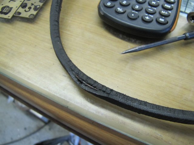
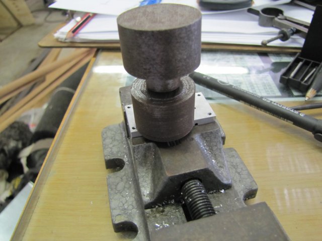
First up, a cylinder along the lines I have in mind - outside admission D-Valve, 10mm bore, 14mm stroke, 5mm thick piston - a rough C-o-C of the plan, and a block of aluminium to make it from:
The block's a bit big; it's 1" square stock about 43mm long. My design calls for a cylinder block 20mm long, 16mm high and 18mm wide. So I milled it down to 20mm in thickness first:
Really hogged it to 20.5 mm hence the big chips, then took the last 0.5mm off slowly to get a better surface finish.
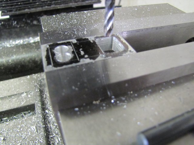
As the block had more than enough material left on it to also make the steam chest from, I slit off the top to make the steam chest from and leave the block 16mm high, rather than waste all that aluminium by turning it into chips:
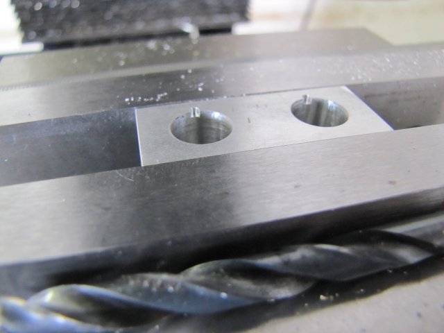
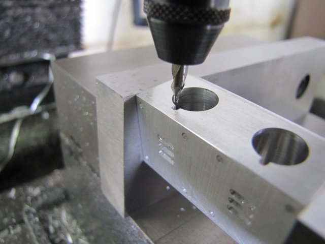
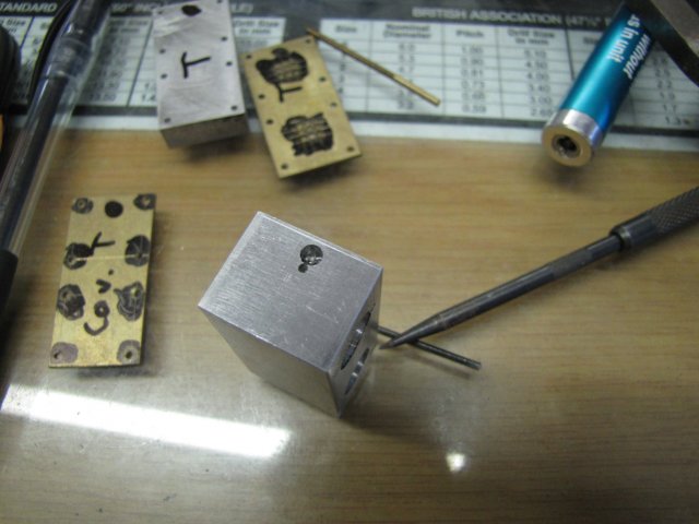
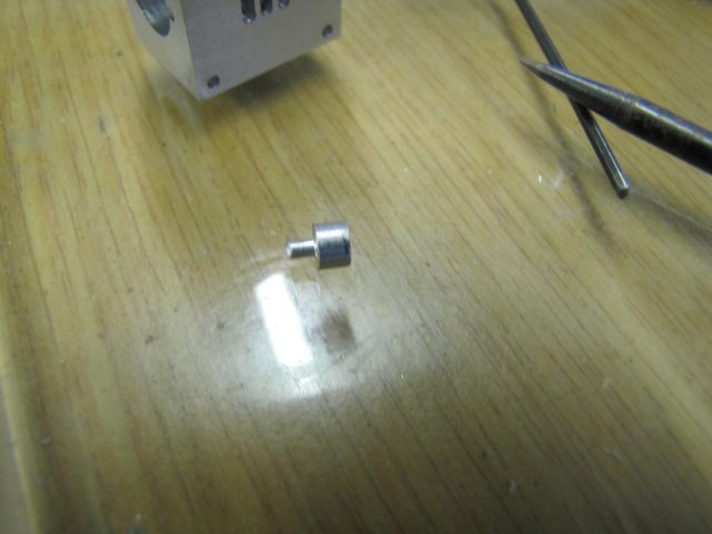
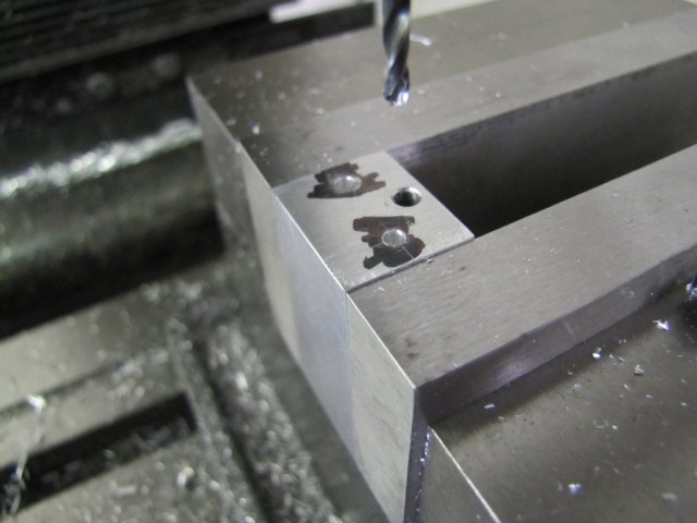
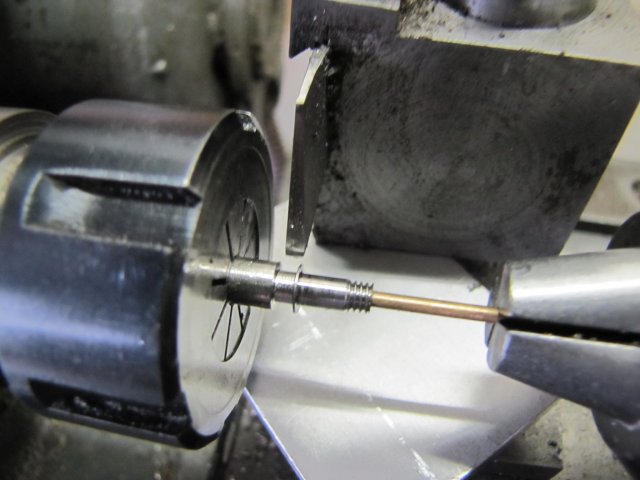
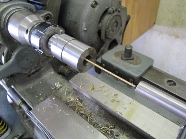
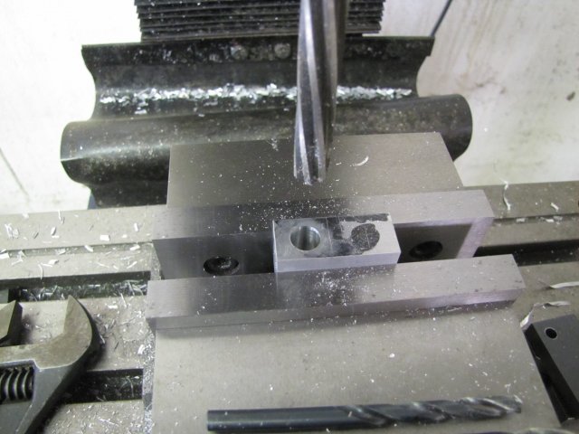
At this point one of the realities of my endeavour kicked in; this cylinder would be quite small... Not nearly as small as Elmer's Tiny, but still, it would present some workholding issues. In fact, there was enough material on that aluminium block to make two cylinders from - while making machining easier..., So I started making two cylinders from it. I marked it out for two, then drilled the first cylinder; a 6mm through hole (just convenient to fit the mill's collet chuck), then 9.8mm, and finally reamed it to 10mm. The reamer is actually a hand reamer that I chucked in the mill - slowest speed and lots of methylated spirits which I use for cutting fluid on aluminium, and it makes for quite a presentable bore:
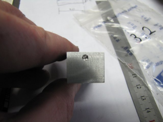
The cylinder bore on the right-hand side received the same treatment
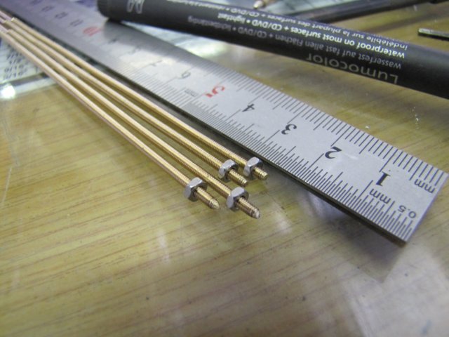
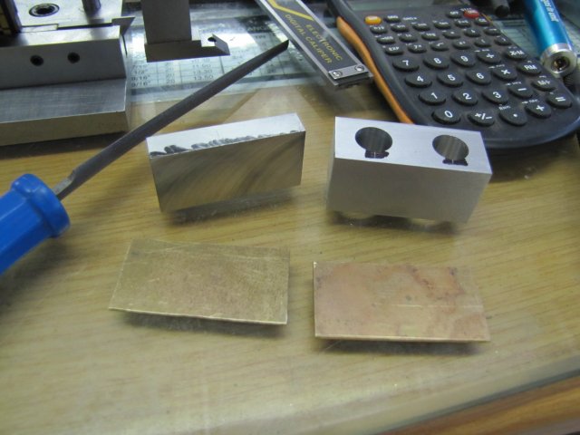
With two cylinders-in-making needing port holes drilled, it just seemed logical to have a think around what's needed in terms of valve chests, valve plates and covers. Cue some small bits of 1mm thick brass:
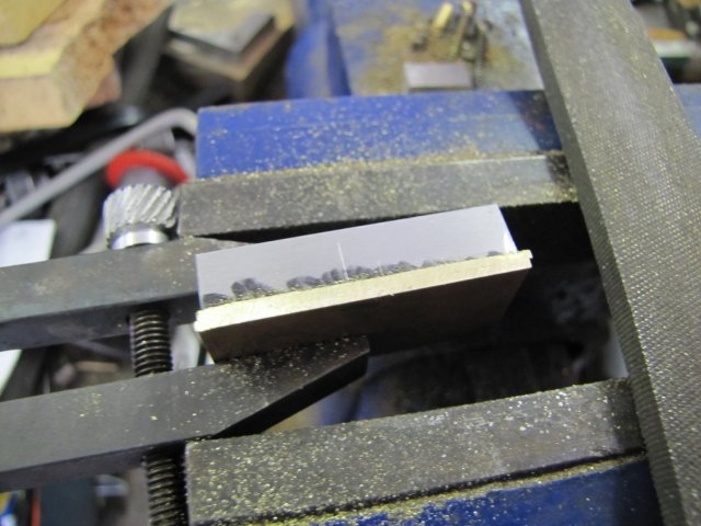
I couldn't be bothered to set up to mill the plates to size, so a quick bit of filing was in order. Good for some exercise to work off the effects of Christmas and New Year
:
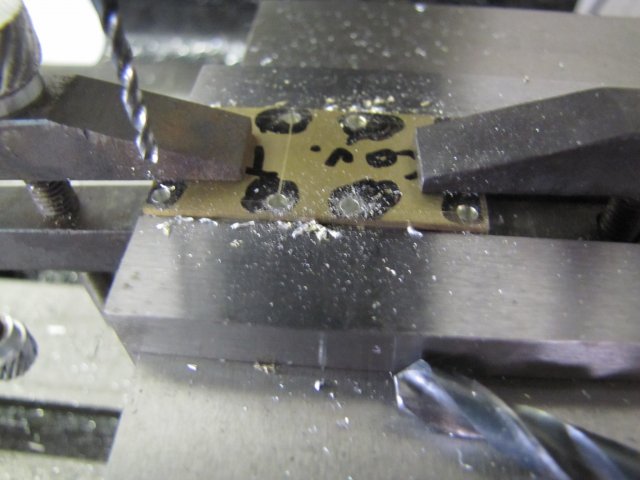
I thought I'd be clever and stick the bits together with some cheap CA glue (Superglue/Crazy Glue):
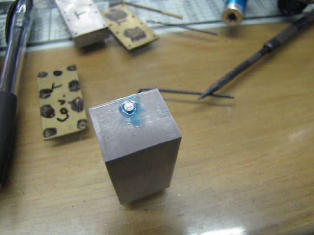
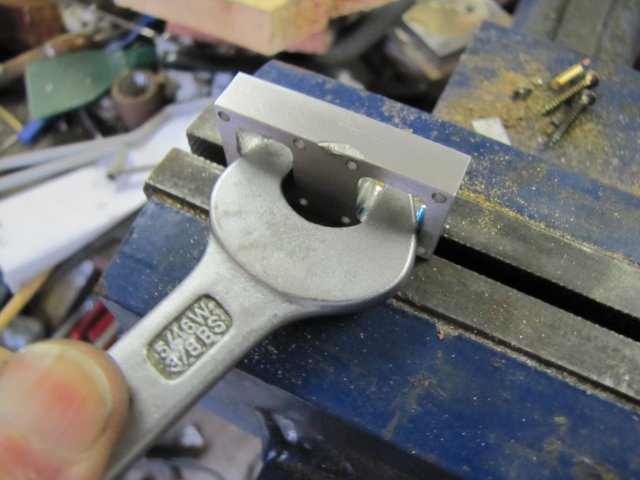
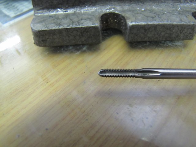
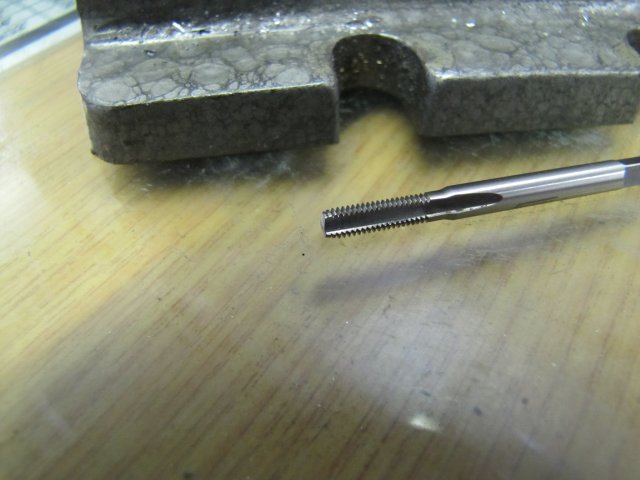
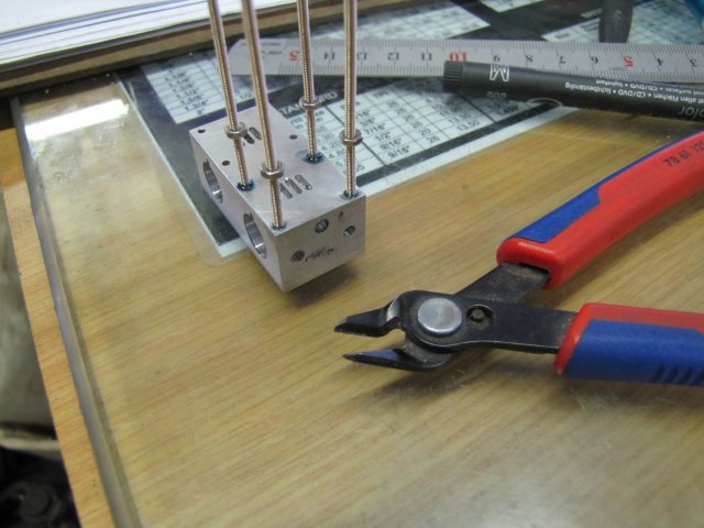
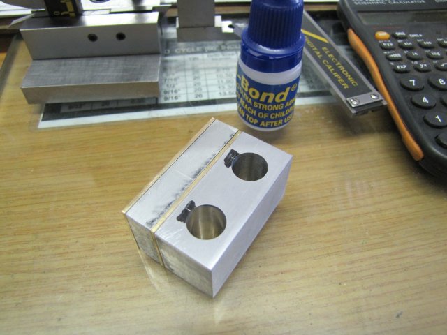
I did say CHEAP CA glue; it didn't work, and while drilling the first 1.6mm bolt hole, it started coming apart, so I fell back to some of my "friends" for keeping things together; the much underestimated toolmaker's clamp:
The bolt hole is 1.6mm for threading M2 - most of the holes will need drilling out to 2mm clearance later on.
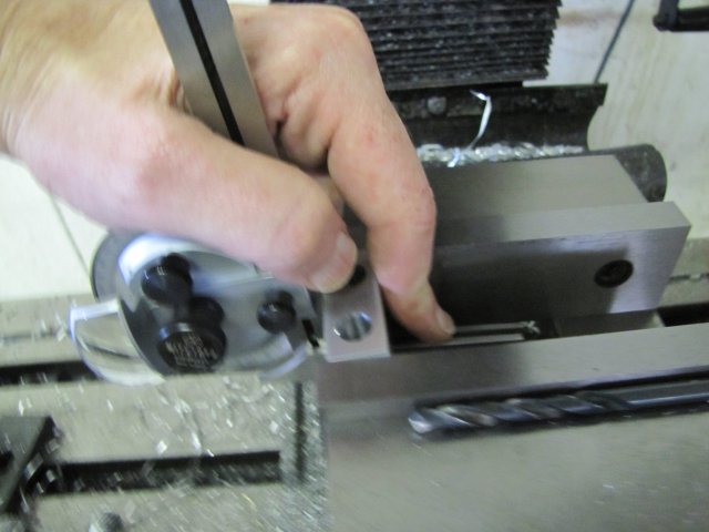
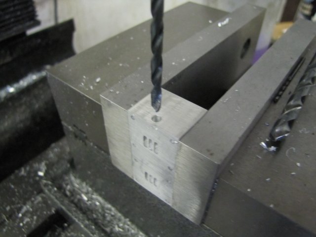
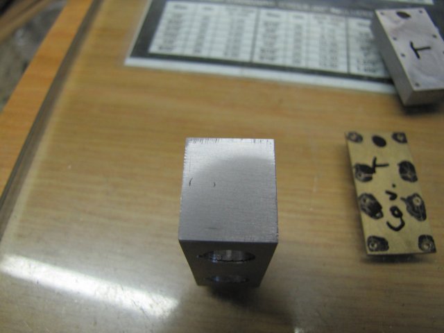
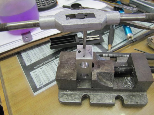
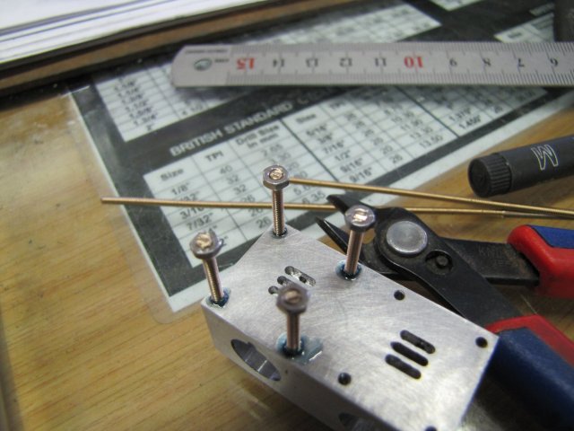
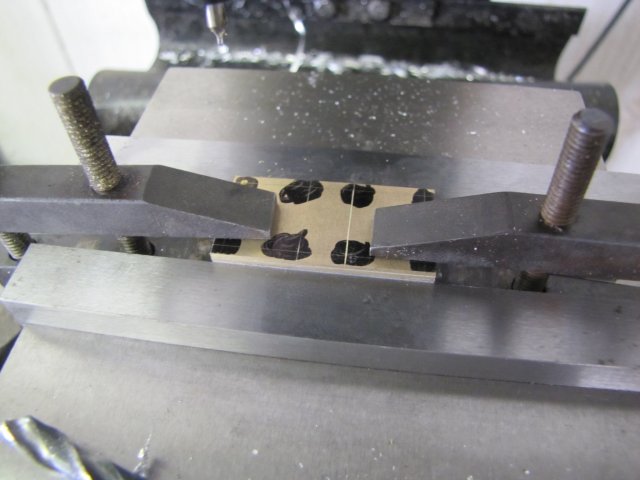
While the going was good, I kept the valve plate fixed to the cylinder block, and laid out one side of the valve holes:
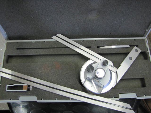
The other side was done simply; clamp up on the side that was done, and remove the clamp on the side to do. Have I mentioned how convenient the height gauge is for jobs like this ? - I can't believe I took so long to make one!
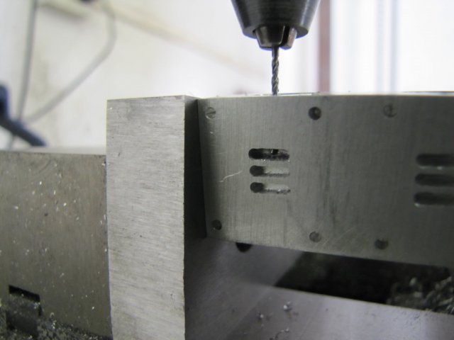
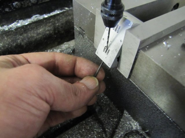
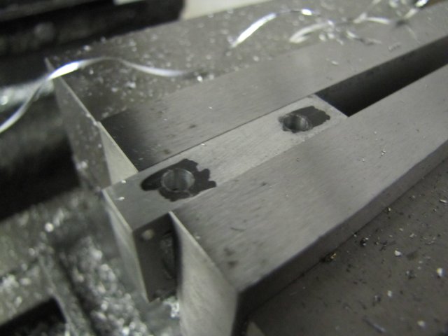
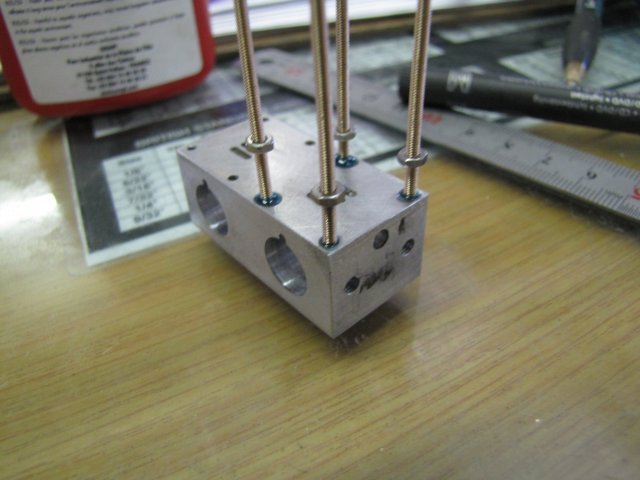
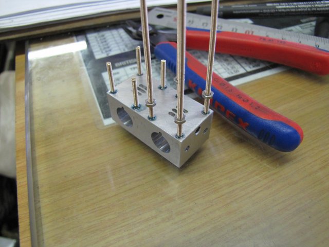
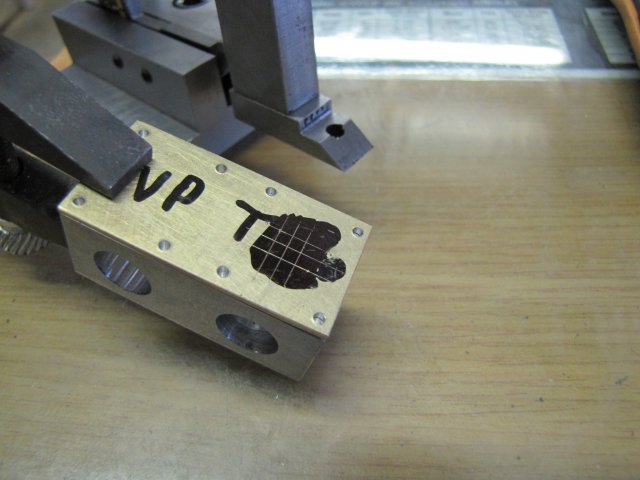
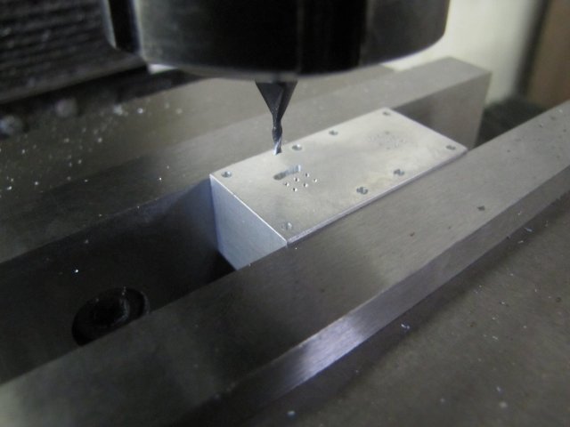
Some drilling in the mill followed. I didn't bother to center punch any of the holes (In fact, I've stopped center punching any hole spots for the last couple of my builds!) I just located the first (top left hand) drilling position as accurately as I could, zeroed, the dials on the mill, and co-ordinate drilled the rest off readings of the handwheels - keeping backlash in mind:
The center drill I used (actually a spotting drill followed by a normal drill would be better - but I don't have spotting drills) has a convenient 1mm tip - but it does make a larger hole - it ends up at about 1.1mm - but OK for the valve plate and spotting through to the engine block.
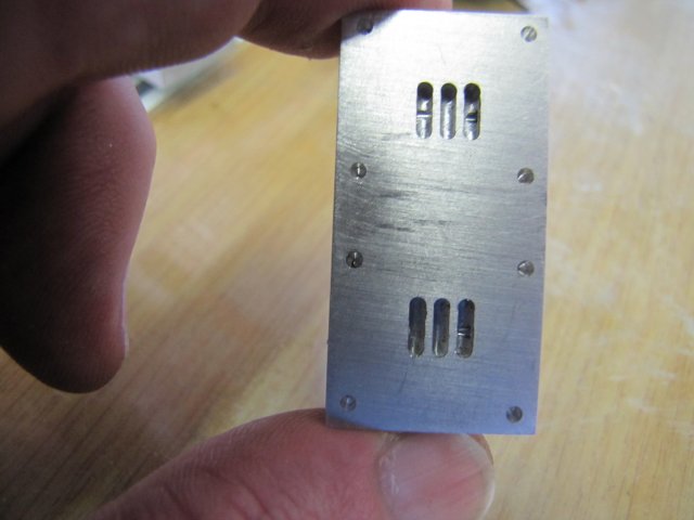
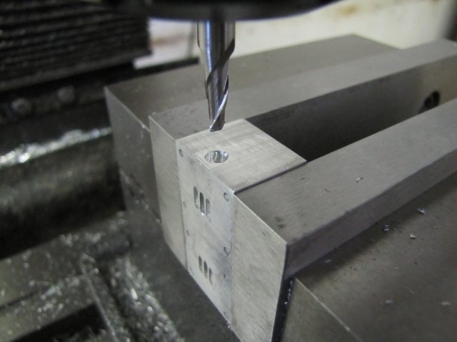
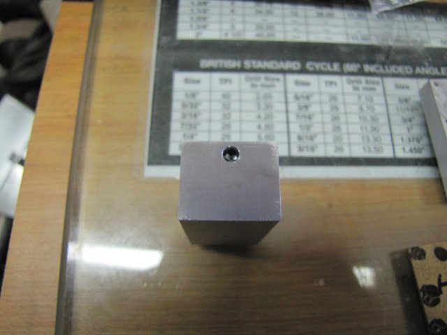
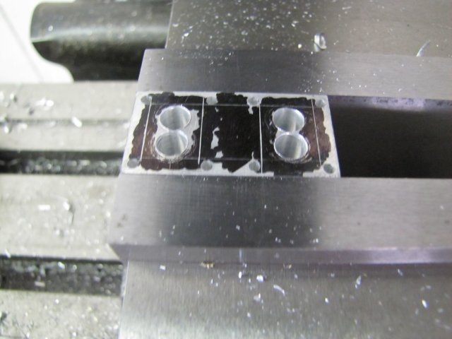
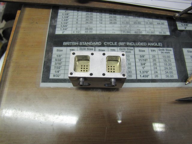
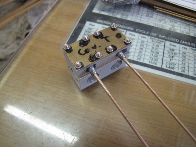
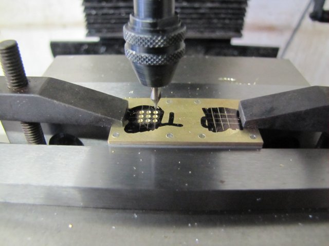
Some milling followed. Seeing as I'd done things by setting the mill dials, this was quite easy. My smallest milling slot cutter is 1.5mm - this is bigger than the 1mm holes I need. By using the valve plate with pretty near correct sized holes, I could slightly offset the bigger cutter to mill the steam and exhaust ports in the block. The steam ports are offset 0.25mm to the outsides, and the exhaust port smack bang in the middle. This leaves a 0.75mm wall between steam ports and exhaust on the block; a bit tight, but it should do:
The ports look a bit crappy in the photo, as there's a lot of burrs. Some flat-lapping removed those, and things are looking up
That was it for today's work; not a lot to show, but some chips to start off the new year ;D:
Regards, Arnold