Valve timing and "fancy" stuff

Home Model Engine Machinist Forum

Help Support Home Model Engine Machinist Forum:

This site may earn a commission from merchant affiliate links, including eBay, Amazon, and others.

Deckel

Member
Joined
Feb 1, 2009
Messages
14
Reaction score
0
Hi all

I was reading a book on steam engines (most of their examples were pretty big, around 25in piston diam...)
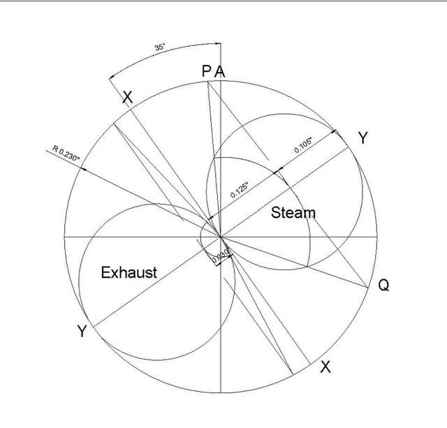
and they were explaining how does steam/exhaust lead/lap work, also some design of double ported slide valves,
the relation between valve and piston speed with different linkages, and other "fancy" stuff.
I would like to know if any of you, as modeler, or full size (reasonable size, as for small boats) engine maker, ever think
about these things when you design or build an engine, or, as me (yet), don't bother much an let steam in and out at TDC and BDC
and smile looking at the engine running cause it will still runs pretty well anyway!
I don't know if they use these kind of techniques only for huge engine since it does influence the power and efficiency,
or even for small scale engine these things are "critical".

Thanks, Deckel
 
Deckel,

I don't know about others but I used valve timing when I made a model mill engine. The timing diagram is shown below.

Zeuners.jpg


Best Regards
Bob
 
Bob, I haven't seen that diagram before. Could you give a brief explanation? Mike. Great work on your engine by the way. MM
 
Deckel,

I have used "graphical" calculations similar to the picture shown by Maryak to improve the performance of some second hand model engines I have bought over the gears be resizing the ports & slide valve dimensions.

The method I have used is the ZEUNER DIAGRAM. Its "construction" is explained in "Model Engineer's Handbook" by Tubal Cain.

It is also described in the google book :

http://books.google.com.au/books?id=mTLtIpYJN0UC&pg=PA519&lpg=PA519&dq=zeuner+DIAGRAM+steam&source=web&ots=6V6FJdJkvQ&sig=80KFvRz7d5XwUt5I76GVjKWTQEA&hl=en&ei=Xm-PSYq1DdKukAX56o3RDA&sa=X&oi=book_result&resnum=8&ct=result#PPA522,M1

 
Hi Deckel, to answer your question completely would take almost a book but I'll try and give you the short version. Steam is an expansive gas. What does this mean? It means that it has power in the heat of the steam. If you run an engine on compressed air when you cut off the supply there is no longer any push on the piston but if you use steam when the valve closes the expansion of the steam is still doing work in the cylinder. How does this apply to valves and overlap and cutoff and all that fancy stuff? Well with this power available there is no reason to have the valve open for the full stroke of the piston, in fact the steam is generally cut off at anywhere from 1/2-5/8 of the piston stroke. This saves steam and therefore fuel. To accomplish this cutoff various valve arrangements were made but ultimately served the same purpose, to save fuel. Another fact about steam valving is the fact that the exhaust side of the valve would close before the piston got to the end of it's stroke. This would serve 2 purposes, one to cushion the piston and rod assembly at the end of its travel and the other was to build up some pressure in the cylinder which would then require less steam to be used on the filling cycle. As far as model work goes, it's nowhere near as necessary to apply all these factors because model engines aren't used generally for work and saving a penny on steam generation isn't a big concern to the hobbiest. I do find it's very interesting to know that steam engines weren't just crude machines that belched smoke and used water. In their later life they were quite sophisticated mechanisms. The Corliss is one of these examples.
gbritnell
 
OK Mike,

The attached PDF explains the Zeuners diagram.

As Gbritnell said in model work it is nowhere near as necessary as in 12"=1ft., and I doubt that my playing around resulted in any noticeable savings. However it was of interest to me to have a go and see what came out of the lap, lead, exhaust lap equation, so I did. It was a fun exercise. :D ;) :)

Best Regards
Bob

View attachment Slide valve designing.pdf
 
Thanks for the replies guys

Just wanted to say the book I was reading is " modern steam engines " by Joshua Rose
Written in 1887, and as gbritnell mentioned, these engines really weren't just big piles of twisted steel, and the engineers behind them were completely amazing.
Considering they didn't had any computers or whatever software to support them, they were real genius.
Deckel
 
Maryak said:
The attached PDF explains the Zeuners diagram.

Reading is Fun. Thanks! :)

As Gbritnell said in model work it is nowhere near as necessary as in 12"=1ft., and I doubt that my playing around resulted in any noticeable savings. However it was of interest to me to have a go and see what came out of the lap, lead, exhaust lap equation, so I did. It was a fun exercise. :D ;) :)

That last part is the most important but a few nagging questions I hadn't dared ask about port timing were answered in a way even I could understand so it's all good.

Best regards,

Kludge
 
Thanks Deckel for a really interesting question, learning a lot from the answers. Bob, your a star as usual....more reading......good stuff......MM :bow:
 
Hi All,

Just to complete the picture. ::)

For a slide valve with equal lap and lead at the top and bottom, there is a difference in the timing between the up and down stroke caused by the connecting rod and crank angles going up versus coming down. This difference is accounted for by making the bottom lead bigger than the top lead and the top steam lap bigger than the bottom steam lap.

I hope your less confused than I was when I started out. :eek: :eek:

Best Regards
Bob
 
Maryak said:
I hope your less confused than I was when I started out.

No confusion here, Bob. Chaos, yes, but no confusion. ;D

BEst regards,

Kludge ... whose eyes are crossing even more
 
Hi all,
I had some time to look at these diagrams which I start to understand (barely).
Did I missed something or the info we got tells how to do these diagrams in order to find lead angle, eccentrics position on crank, but never how to determine what lead, lap, cutoff should be used ?
Also, it is mention that each side of the piston have different setups, but what if it is a reversing engine, should both side be the same or it doesn't affect anything ?
And if it is a compound engine, both cylinders should have the same setups, or only the hp one have cutoff ? (if cutoff is used in compound engines..)

Thanks, Deckel, who is now working on a reversing compound 1.75+3x2, and might stop and return to drawboard before going too far...

 
Deckel,

Try this link where it explains how the cylinder port size is determined which in turn determines the valve properties. http://www.steamtraction.com/archive/2722/

Even if its a reversing engine the valve settings are effected by going up v coming down. So basically they are the same irrespective of crankshaft direction.

Yes compound engines have lap lead cut off etc on both valves but they are different due to the different cylinder, port and valve sizes required as the steam decreases in pressure and increases in volume from the HP exhaust. If you increase the length of admission in the HP, the power of the whole engine is increased and vice versa. By playing around with the cut off on the LP, (2 cyl compound engine), you try to achieve a balance so that each cylinder is doing the same amount of work, ( developing the same IHP).

Hope this helps ???

Best Regards
Bob


Latest posts

Back
Top