Valve design

Home Model Engine Machinist Forum

Help Support Home Model Engine Machinist Forum:

This site may earn a commission from merchant affiliate links, including eBay, Amazon, and others.

Brian Rupnow

Design Engineer
Project of the Month Winner
Joined
May 23, 2008
Messages
15,011
Reaction score
8,307
Location
Barrie, Ontario, Canada
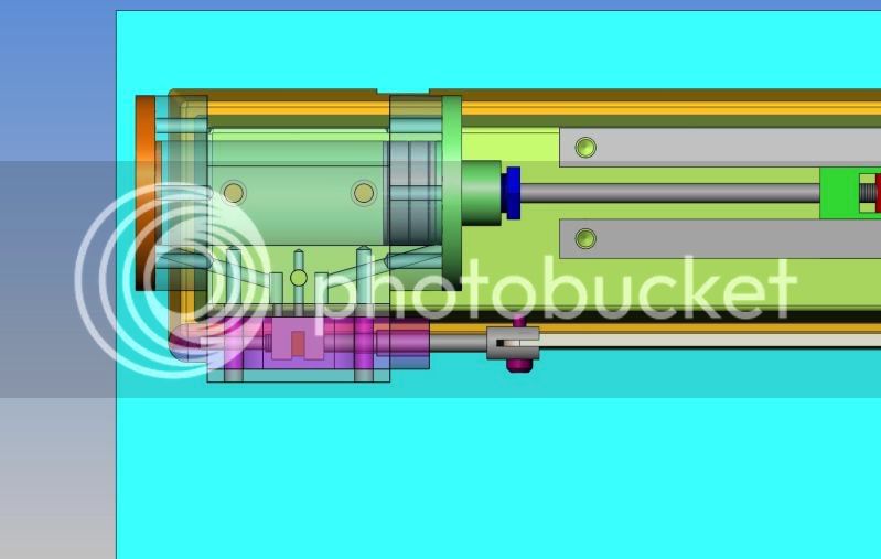
Although I have been playing about with model steam/air engines for 2 years now, I still do not have a clearly defined understanding of valve design for a double acting air engine. If we leave "lag" and "lead" out of the equation, I want to know the following information. For a "given" stroke and piston length, how does one go about calculating A--The "throw" on the valve eccentric, B--the length of the "big ends" on the spool valve, the distance between the inlet and outlet ports, C--the distance between the "big ends" on the spool valve. I am sure that this information can all be reduced to a set of formulae that will cover any double acting air engine, but I haven't been able to find it, and I don't seem to be able to figure it out by myself. This all shows up in the attached .gif which was so kindly provided by Maryak. If anyone can help withthis, it would be an immense help to myself and to all other model engineers.---Brian
PISTONV1.gif
 
Most of those numbers depend on where you start with the valve. You can start at the crank end with some throw on the eccentric, and then figure out how far apart things need to be at the valve. Or you can figure out what you need for the valve and then figure out what eccentric will give you that motion. If you want a reversing linkage yu need enough valve travel that you can put the extra linkage in and still have the valve work.

If you have a CAD program you can play with the details that way and have them work pretty good when you get them in hardware.

And you will notice that a lot of the linkages have some sort of threaded connection in the linkage that allows for some adjustment in case you didn't quite measure of make everything perfect.
 
kf2qd--I am aware of what you are saying, and I do have a very advanced 3D cad program, however that does not answer the questions I asked.
 
The stroke and piston length don't really have much impact on your valve design Brian. I usually start with a convenient* set of ports and work out the valve and eccentric details from that.

*convenient* in the sense that things have enough room to work comfortably on the available port face area.


cylinder#9.jpg
 
Tel---I respect your knowledge a great deal, and I wish I lived close enough to you that we could set down together and work thru this. The issue is that you know things so well that you assume others have that rudimentary knowledge, and thats not always the case. Okay---starting with the statement you made, I see 3 openings in the cylinder "port face area". I assume that one opening ports to one end of the cylinder, the second ports to the opposite end of the cylinder--is that a third port in the center?--and if so, where does it lead to?.
 
The centre port is the exhaust port, with the outer two, as you rightly deduce, going to either end of the cylinder. The slide valve has a cavity on the underside, and when the port one end is open to inlet, the other end has the cavity bridging the two ports, and the exhaust exits through a hole (yet to be drill en that one) in the side of the port block.
 
Brian,

Here's an animated graphic that might make the whole operation a little clearer. This is a locomotive engine, but is basically a double acting, reciprocating engine.

http://www.animatedengines.com/locomotive.shtml

The valve timing on these types of engines is typically about 90 degrees out of phase with the piston.

Chuck
 
Ya beat me to it Chuck - I was just over on Matt Keveney's site getting the link.
 
Brian:
I have a book on steam engine design IIRC a Lindsay reprint from PM Research. The original Was International Text BOOK CO. If you search google books or archive.org and search for steam engine design you should find lots of info.
Tin
 
A pair of valves, with a very roughly cut cavity, along with the hi-tech computations to get the sizes.

 
FWIW, Tel is making a slide valve, while the original picture shows a piston valve. If you don't really want to do a piston valve, I think working out the slide valve is easier.
 
Brian, there are all kinds of formulas for calculating events on steam engine. There are only a few that you would need to design an operating valve for one. One of the first things to take into consideration is the length of the cylinder itself. I say this because generally the valve, piston or D valve, and it's working chamber is no longer than the length of the cylinder. With that dimension set the next thing is to have the valve travel within that distance. That will determine the stroke for the valve eccentric. The animation you show is an outside admission piston valve. There is also an inside type admission. This only has to do with what side of the valve is admitting steam to the cylinder. The actual port size would be determined by the volume of the cylinder and the operating RPM. In automotive terms it would be the amount of flow required to operate the engine efficiently at a given RPM. For general model work it's not that important of a number. The next thing to consider is that 'steam' works with a cut off specification, 1/2, 5/8, 3/4 stroke whereas air can be admitted for the greater part of the stroke because it has not 'power' like steam does. The purpose of the valve is to admit the pressure on one side of the piston for a given period of time while allowing the exhaust to exit from the other side. As the piston nears the end of it's stroke the valve will change position, as was previously stated about 90 degrees in advance of the piston to allow these events to start over again. Lacking a Cad system to lay out some key dimensions you would have to resort to good old paper and pencil. They did it back when there were no computers.
gbritnell
 
I find this all quite intriguing. I have never built the type of valve which Tel shows, only the spool type as shown in the .gif. In order to understand this properly, I will have to model an engine with this type of valve on it. Can anyone give me a link to free plans for a simple single cylinder double acting engine with this type of valve? Did Elmer have one? I don't want to build it, out I do want to model it to help me understand this valve business.---Brian
 
Brian;

Elmer did several with the valve like Tel describes. The one I know for certain is the #33 a dual acting horizontal.
 
Is this enough to model from?

No dimensions, soprobably not.

cutawaysteamengine.gif
 
One thing hasn't been mentioned about this type of valve...

The valve itself is not rigidly attached to the valve rod that transmits its back and forth motion. A nut on that rod rides in the slot on the top of the valve - the valve is forced to move back and forth but it can ride up and down a bit on that nut.

Now the upper part of the valve is in the steam chest so its surface is always pressurized to whatever the steam pressure is. On the other hand, the cavity on the bottom of the valve is always sitting over the exhaust port so it has only atmospheric pressure acting on it.

The net effect is that there is a constant pressure differential across the valve and this differential acts to force the valve down against the valve plate on which it rides, thus increasing the sealing of the valve. Very clever.
 
Dang, there's a lot of parts to that engine!!! I've been modelling ever since that last post. I'm off to eat some lunch, will assemble this afterwards.---Brian
ASSEMBLY-33-PARTSONLY.jpg
 
Back
Top