Universal Joint

Home Model Engine Machinist Forum

Help Support Home Model Engine Machinist Forum:

This site may earn a commission from merchant affiliate links, including eBay, Amazon, and others.

Brian Rupnow

Design Engineer
Project of the Month Winner
Joined
May 23, 2008
Messages
14,991
Reaction score
8,285
Location
Barrie, Ontario, Canada
This is something that's been coming for a long time. Every model machinist, wants deep in his heart of hearts to make a universal joint. You have to reach a certain point of confidence in your ability to machine things and be bored enough to consider a project like this. The worst thing is that one universal by itself isn't much good. To really show them working properly, you need two of the darned things working together. I'm kind of dancing from one customer to another on small jobs with free time and wait periods in between spots of real work, so I think I'll try and make a couple of these.
 
Excellent timing! I am in the process of building a large (nearly 5 feet long and will weigh 65lbs or so) radio controlled tug boat that has 2 24volt motors powering 2 4" propellers. I need some u-joints just a bit smaller than this, but the same design.

Lead on McDuff!

Tom
 
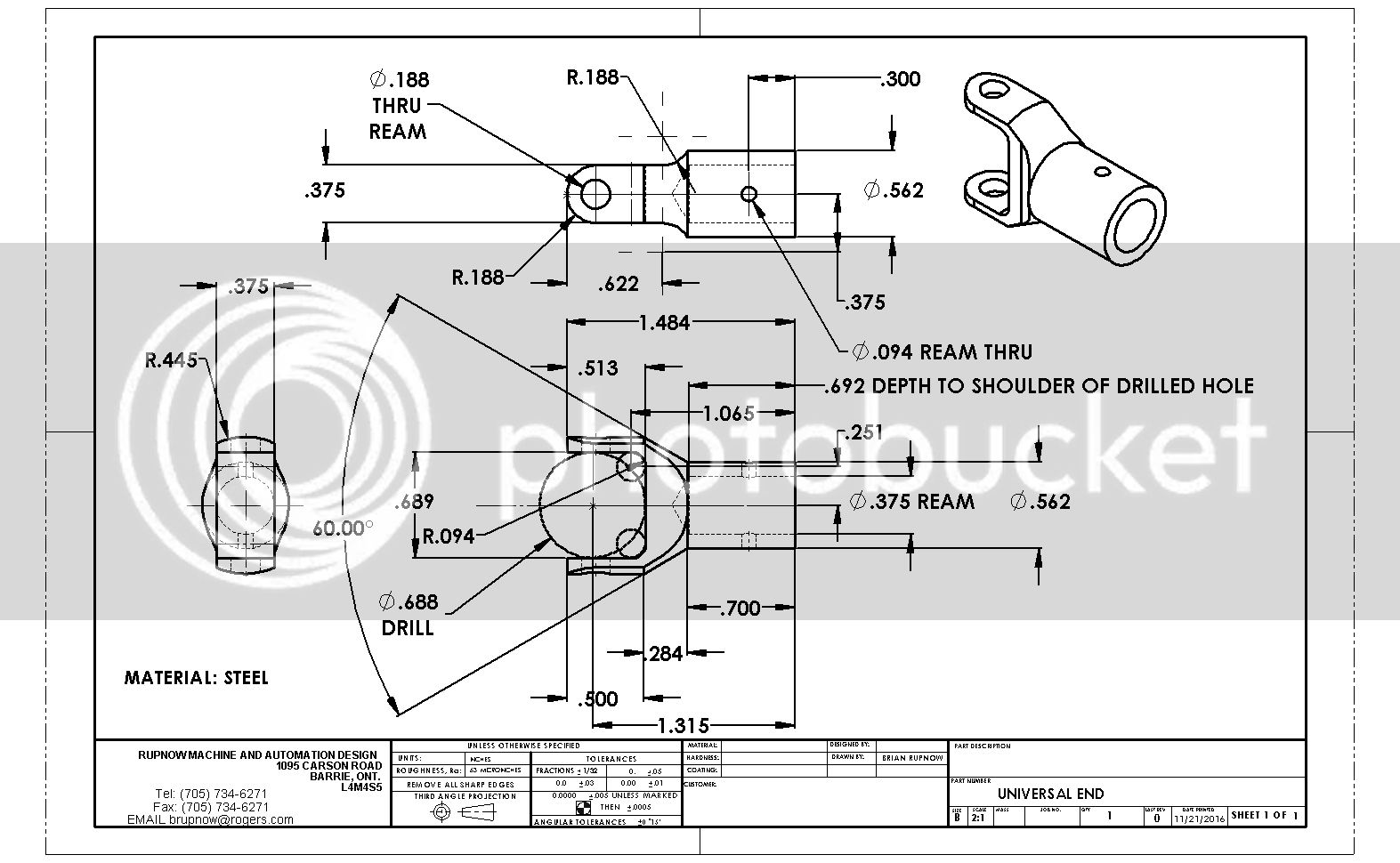
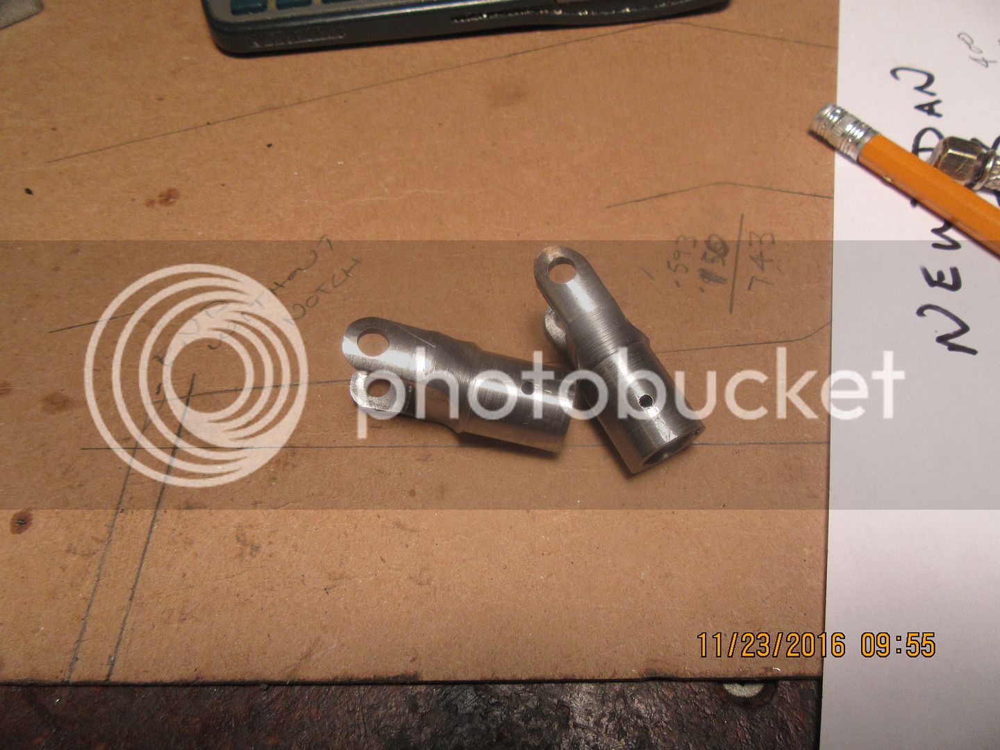
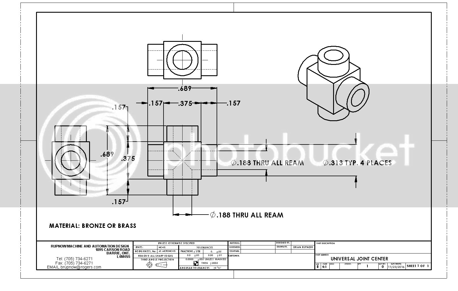
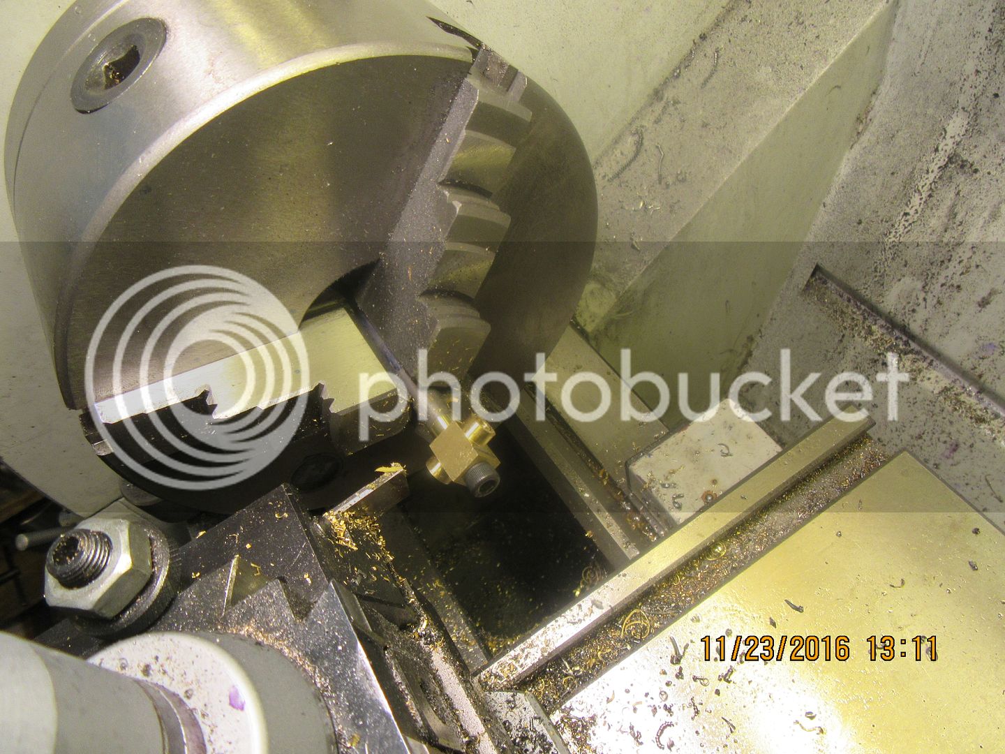
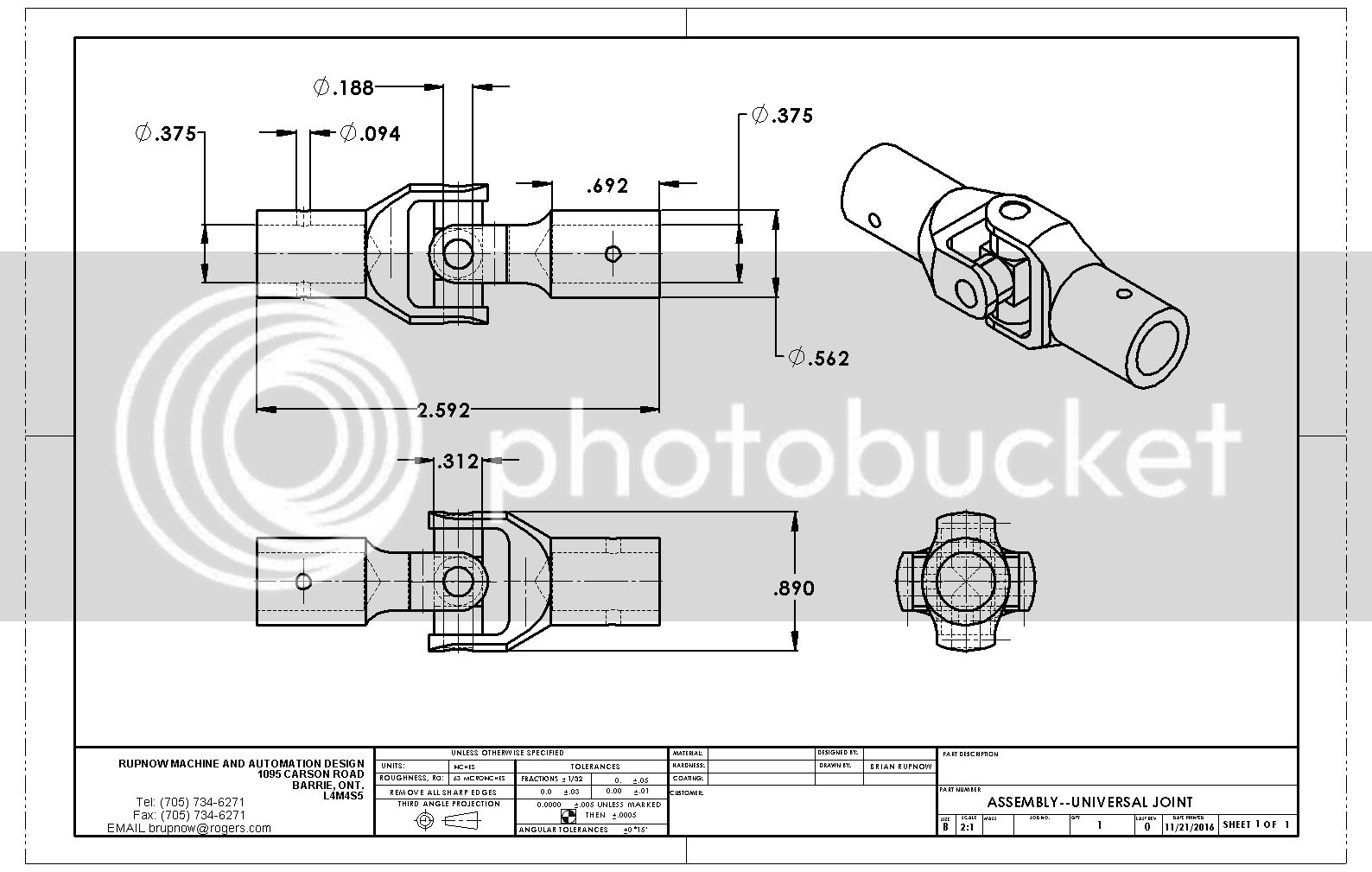
I made a start today, then got busy with a bunch of "real work" and that eat up the rest of my day. At any rate, this is the drawing I'm working from, and this is how far I got on the part. Taken down from 1" stock to 0.890" diameter, taken down to 0.562 over part of the length, drilled and reamed as per drawing, and 60 degree taper machined in, all in the same set-up.

 
FYI
When welding or drill, both yokes need to be parallel
Most welder just uses a low cost 9" leave

Dave
 
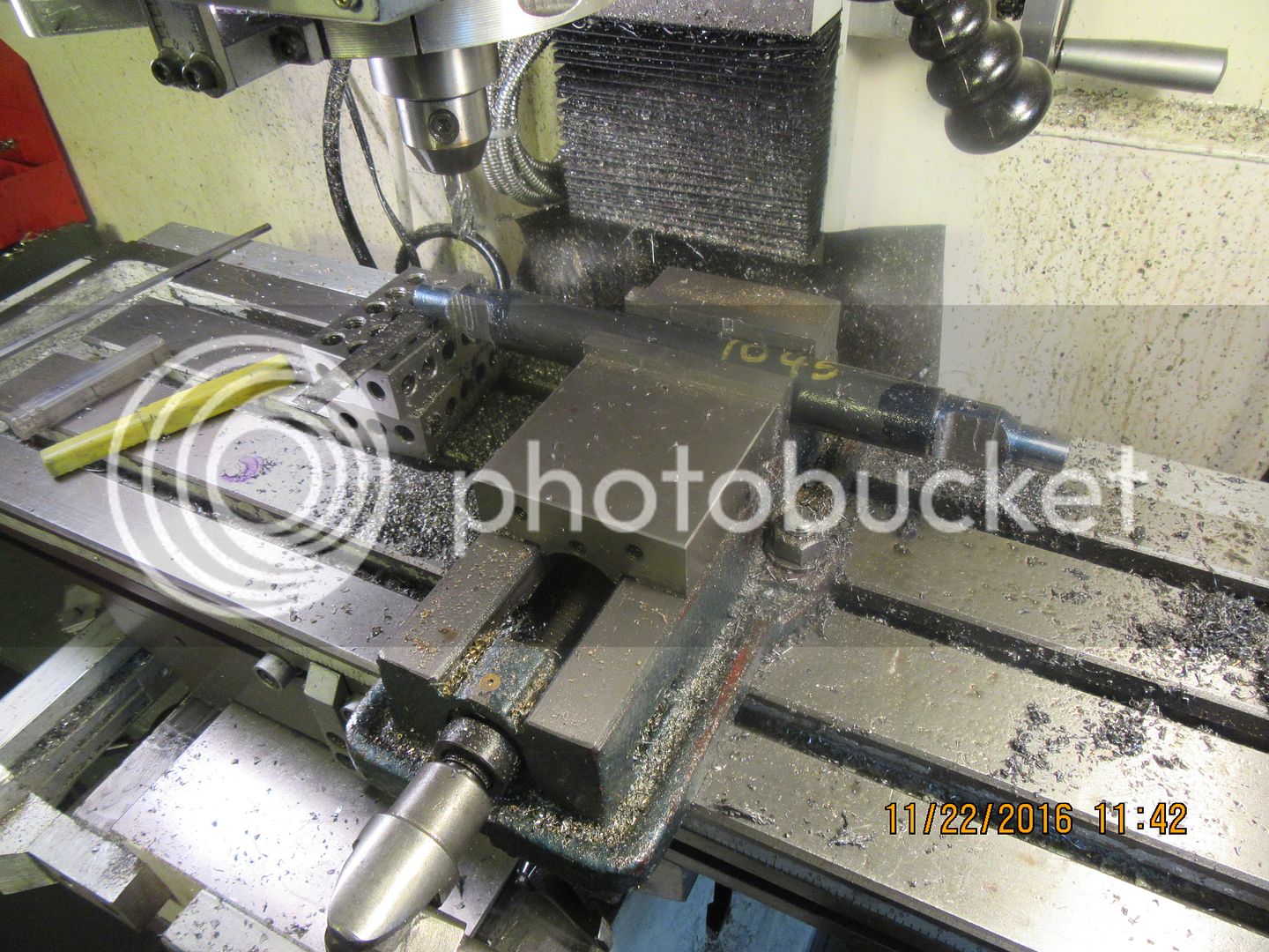
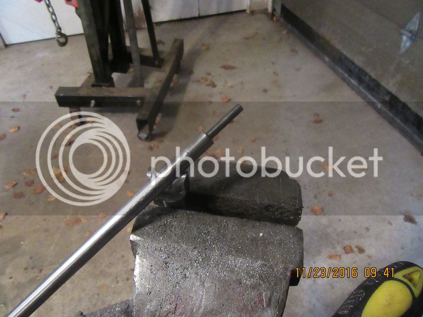
So here I am, making it up as I go along. I'm working with two bars of different material so I can judge which one seems to cut best with my machinery. The one in the vice is 1045 steel, and it machines relatively well. The other one is a piece of ground and polished A36, which is not hardened in any way. The A36 doesn't machine near as cleanly as the 1045--it tends to smear and tear rather than cut cleanly.
 
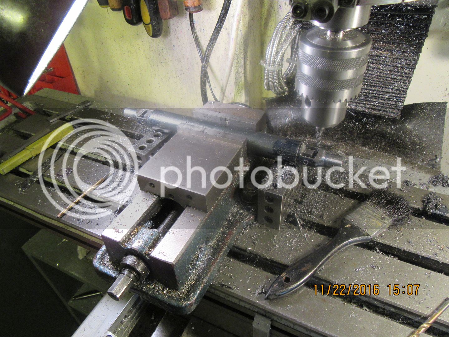
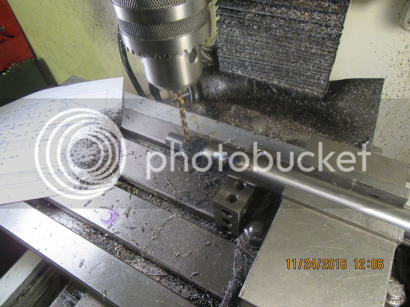
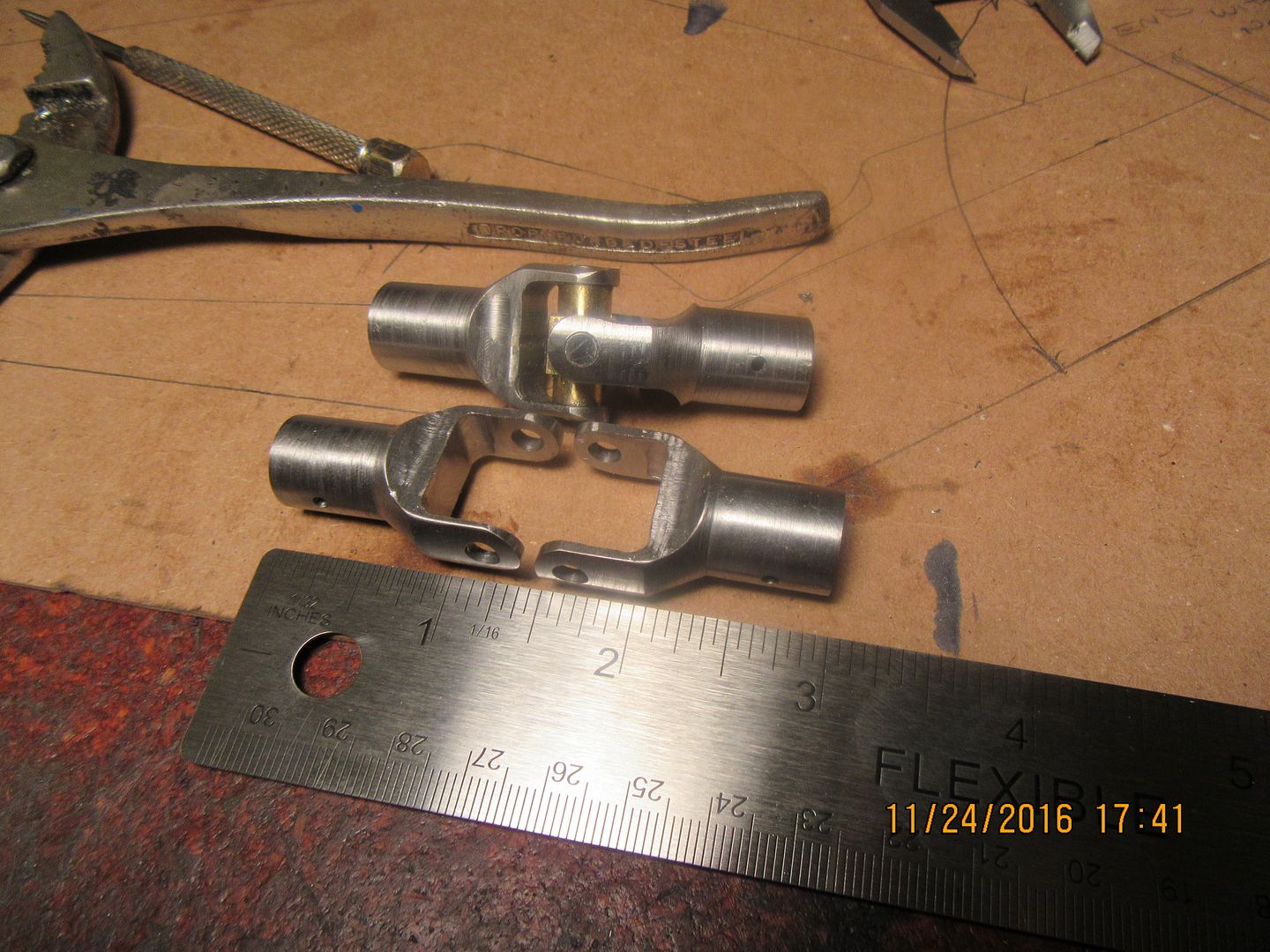
Here you can see an "in process" of cutting the centers out of the universal joint ends. I futzed around a bit just figuring out how I was going to do this, then drilled a 3/16" hole at each corner of what would be opened up and then just "chain plunged" with a 3/16" endmill all around between the holes, running at about 750 rpm taking 0.020" steps between full depth plunges. These are actually turning out too nice to free-hand the end radius. I may have to machine up a couple of filing buttons out of some 01 and harden it so I can make decent looking ends on the pieces.

 
Well---that was a bummer!!! Turned up a nice filing button, heated it, quenched it---then tried it with a file and it cuts like butter. Some donkey put a stick of cold rolled in the drill rod rack. And since I'm the only person with access, well----However, I did find a piece of drill rod the right diameter after the fact, so that will be tomorrow mornings job.
 
well I am really happy you are making a u joint, as I have thought about how one could make a u joint.

I am especially interested in how you make the cross and bearing cups so to speak. I was thinking in my head a square cross drilled in the shape of "+" and threaded, then for the cups a thick head screw. really don't know what to call the bearing cups since this isn't a needle bearing u joint but calling it cups as that is the area of interest for me.

thanks for doing this project Brian.
 
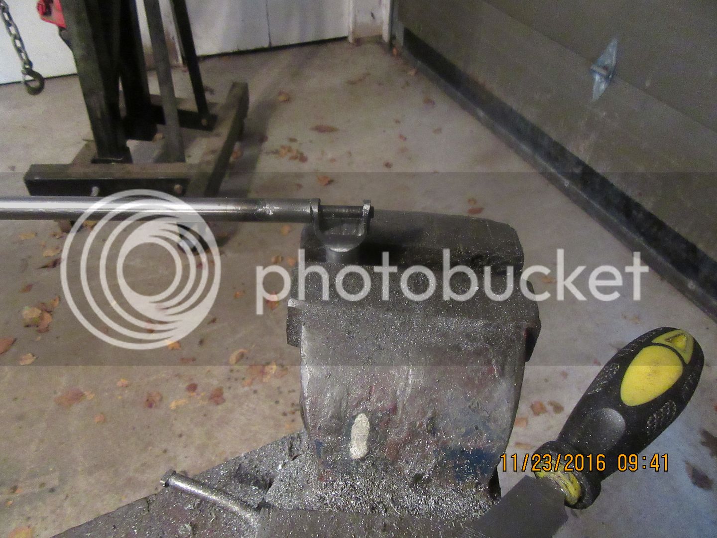
For anyone out there who doesn't fully grock the concept of "filing buttons" it is a rather neat trick. I wanted the radius on the tips of the universal where the 3/16" hole goes thru the arms to be nice and concentric to the hole. You could accomplish this with the proper set-up in a rotary table. You could (if you are very steady and keen of eye), do it freehand on a big belt sander. That is the way I do it most of the time on bigger parts. However, this trick is neat, I learned it of British steam engine web-sites. If you have a piece of drill rod the diameter of the finished end you want to put the radius on, then turn down an area small enough to fit thru the hole, then harden the drill rod by torch and quench method. I didn't bother cutting my drill rod down to a short length to make a "button"---I left it full length on the end of the rod. It doesn't matter. Put the part to be filed in your vice, insert the hardened drill rod, then start filing on the sharp corners of your piece. The file will only cut material until it gets down to the surface of the hardened drill rod, and won't go any farther, because the drill rod is now harder than the devils horn, and the file won't cut it. this leaves a very nice radius on the part you were filing.


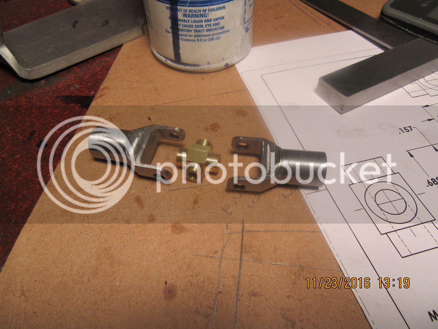
Now I'm at a juncture---I was going to finish all the ends first, then do the center spiders.--but--This looks so exciting I can't wait. I have to make the spider now and finish this first universal joint.
 
The spider is finished, and it turned out really good. There was a nifty trick used in machining that. The material is 3/8" thick. I cut out the profile on my bandsaw, leaving just enough material for cleanup. I cleaned up the 4 cut sides on my beltsander, and cleaned up the 4 notches in the corners of what started out as a rectangular piece of bronze with a file. Set it up in the mill vice and reamed one 3/16" diameter hole thru, then turned it 90 degrees and put the second 3/16" hole thru. Now comes the trick part. 3/16" is 0.188". The outer diameter of a #10 bolt is 0.190" in diameter. A bolt that size will "self thread" thru brass or bronze, cutting a very shallow thread. I tapped a #10-24 thread in the end of a piece of round 5/16" diameter cold rolled while it was set up in the lathe 3 jaw chuck. The socket head bolt goes thru the bronze part and screw into the end of the 5/16" diameter cold rolled steel rod. Then, using a 3/32" cut off tool, and the o.d. of the steel rod as a reference diameter (that is the diameter of the bosses on the spider) I took cuts in .030" increments from the face of the spider closest to the chuck, until the newly cut boss reached the length I desired. Did that 4 times. ran the 3/16 reamer thru each hole once more, and it was finished.

 
You don't need to harden filling buttons. Just make them 2 or 3 times thicker than the part you are filing and they will last just fine if you stop filling when you hit them, if they can spin on the centre pin and you file at right angles to the pin then they roll and don't ware anyway, both ways you stop blunting your best file. I ruined far to many good files on hardened filling buttons before I stopped hardening them, To file a round boss in ,say, 1/4 inch plate I would make two buttons out of 3/4 inch long rod. just think how long it will take to file down a piece of steel1 3/4 inch wide.
I always enjoy what you are doing. Keep it up.

Buchanan
 
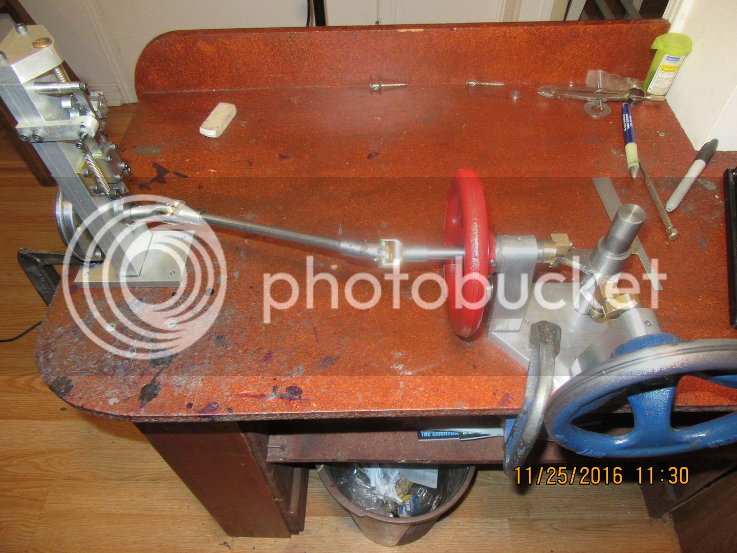
And there it is finished, in one of it's potential new homes. I coat the inside of the bronze spider with good quality grease, tap the pre-cut to length pieces of 3/16" cold rolled shaft almost home (one is a single piece which goes all the way thru everything, two of the pieces are shorter and just butt up against the long one at the center of the spider), and coat the last 1/16" with 638 Loctite before tapping them all down flush with the outside of the universal joint body.
 
As I get a bit deeper into the machining of the second universal, using the A36 material, I'm not seeing a lot of difference in how it machines compared to the 1045 material. Possibly a bit more drag on an endmill when I'm backing out of a plunge cut, but not a big enough difference to worry about. I think that overall, there isn't a big enough difference in machinability between the two different materials to worry about.
 
I left one picture out of the line-up when I was making the first universal joint. This is a picture of the four 3/16" holes that were put in just before "chain plunging" the material away from 3 sides with a 3/16" endmill .
 
Almost there!! If I can get the spider for the second u-joint done tomorrow, I'll have a pair of them. It's crazy--this is a $650 pair of u-joints, if you consider the time that went into them at about $40 an hour for cheap machine shop rates. I can remember buying full sized auto u-joints for about $16 a set.---Says a lot for the economies in automation and mass production.
 
And we're finished. Two more toys to add to my stable of "weird things I can run with my model engines". It has been a quick and painless build, and it's just another of the nifty things I wanted to build---Just to see if I could!!
[ame]https://www.youtube.com/watch?v=Ci9783NXzr0&feature=youtu.be[/ame]
 
I suppose you have one pin/dovel going through the spider and one fork and two short pins in the other direction.
How did you keep the pins from getting loose?
 

Latest posts

Back
Top