Thread cutting - Can not get correct thread profile

Home Model Engine Machinist Forum

Help Support Home Model Engine Machinist Forum:

This site may earn a commission from merchant affiliate links, including eBay, Amazon, and others.
Hi Guys,
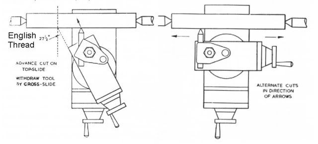
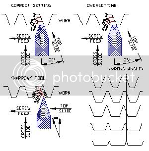
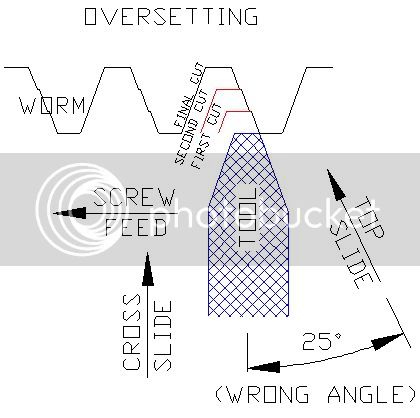
Shall we put a fallacy to bed. When we cut threads we do not make plunge cuts, unless we are making a groove. When threading the tool is moving left all the time it is cutting, this by definition is a sliding cut.
If we want to cut a "V" groove, setting the top slide to half V angle would indeed save chip crowding. When threading we are not cutting a single groove but an helix and on one side only. Think about it!
Not that setting the top slide at half angle is wrong, clearly it works, it is just unnecessary.
As has already been said the advantage of not setting the top slide over is that the thread can be widened once core diameter has been reached. This is very useful if you don't want to grind a new threading tool for each pitch thread you want to cut, remember that the nose on the end should be a match for the pitch, and who wants to do that?
Have any of you chaps looked at a screw cut thread under a microscope? What looks nice and cleanly cut, is in fact more like a file. :eek: Might make you want to take a shaving cut on the right hand flank.
Ned
 
Joe, Your drawing shows the need to grind a special tool for that worm. First the angle is 40° included, the root (bottom V) is 24% of the pitch of the teeth, with a bit of a radius, and appears to be 20 teeth per inch.

Do you have the equipment to accurate grind a cutter that way?
 
Maryak said:
Two ways to single point thread


Untitled-3.jpg

This second drawing shows cutting threads R-L then L-R. Except for a electronic leadscrew, no lathe can do that. There is backlash in the extensive geartrain, then the direction of the leadscrew must be reversed, while the spindle continues the same rotation direction, all without losing the datum point of the thread. Not likely with the lathes folks on this board run.
 
Hello all

I've tried to absorb as much of the info posted but it made my brain hurt. What a can of worms! (pun intended ;D). Thank you to all again. I'll keep reading.

I have had several goes at cutting random and precise threads and have been relatively successful, considering my noobiness at this. Practice will make perfect and this will be another skill to add to my list.

MachineTom said:
Joe, Your drawing shows the need to grind a special tool for that worm. First the angle is 40° included, the root (bottom V) is 24% of the pitch of the teeth, with a bit of a radius, and appears to be 20 teeth per inch.

Do you have the equipment to accurate grind a cutter that way?

I've got enough gear and time to have a go and see what happens. I'll post results when available but after reading Ken's reply below, I think that is what I'll attempt to master after getting a bit of clarification about a couple of things.

Ken I said:
That's correct.

Another way of moving the slide is to make handweel adjustments for the 30° (whatever) so if you feed the tool in 0.2mm then you would offset it forwards by 0.1386 (from trig).

Why bother to do that when you can swing the compound slide ? - well when cutting a worm you can use a pointed tool with a very small flat tip and once you have advanced to depth you can offset the compound slide (in feed rate increments) to "widen" the thread to the correct worm profile - this gets you away from the problems of cutting on more than one edge that I mentioned earlier.

You can also cut to depth then back up slightly to improve the finish on the trailing edge with a light cut and then work your way forward with the leading edge until you get the right profile.

The flank finish on a worm needs to be really good if its not to "mill" away at the worm gear.

This process also allows you to use the same form tool on different pitches of worm and you are not reliant on how accurate you ground the tip flat.

Regards,
Ken

Ken

Please bear with me...

I understand the concept of what you suggested but would you please elaborate on parts that I boldened (?).

In particular:

Swing the compound slide - Does this mean to change the angle from, say 30, to a different value? If so, what angle?

How do you offset the compound slide (in feed rate increments) to widen the thread.

I will now try to grind a tool with a 40 deg angle and a slightly flattened nose...

Regards

Joe


Joe,
The topslide (compound slide) should be at 1/2 the included angle so that you advance parralell to the trailing edge flank angle - whatever that may be.

As per Maryak's drawings

For Metric & US threads 60° - hence 30°
For Whitworth 55° - hence 27½°
For Worms - 40° - hence 20° (That is for use with 20° pressure angle involute gears).

So you take a cut, advance the top slide - repeat. The second and all subsequent cuts will only cut on the leading edge - so you get only one chipstream, no interference, less load and better finish.

As I said you don't have to do this but it is the "propper" way.

As some of the other posts have suggested use slightly less angle - ie for a 60° thread - instead of using 30° use 29.5° that way the trailing edge is going to remove some material (but very little) at the same time.
The main reason for this is if your setting is actually 30½° then your trailing edge flank is going to have a series of slight steps in it so its better to err on the underside rather than risk being over.

Be carefull of this "underset" approach when machining work hardening materials like EN30B and some stainless - the light cut on the trailing edge will simply rub and burn the cutter.

Now - if we don't set the topslide angle we can accomplish the same thing by moving the topslide in the direction of feed by the trig value.
Take your 40° Worm

If we feed in the cross slide 0.2mm for our next cut then we need to also advance the top slide by 0.2 x Tan 20° = 0.0728 to the left.
This will accomplish the same thing (as swinging the top slide 20°).

However its a lousy inaccurate method for threads (because of rounding, erorr stackup, handwheel, indicator, screwthread etc. etc.) errors - but for a worm it is useful to leave the top slide in its normal position so that we can use it to adjust left and right to widen the groove - so small flank errors will be removed on the finishing cuts anyway.
Screwcut.jpg


In the above I have tried (rather badly) to explain.

Top left with the top slide swung to half the angle.

Top right - what happens if you overset. You will get steps in the trailing flank.

Bottom left - using a "narrow" tool - go in in a seies of in/left adjustments using the cross slide and top slide to simulate coming in at 20° (I'm not suggesting you do it in so few cuts - exaggerated for effect). Once you reach depth adjust the top slide to the right to take a "smoothing cut on the trailing edge flank.
Then to the left in steps until you get the correct profile width.

I have attatched the Autocad sketch if this helps.

AHHHRRGGHH - its like wading through muddy water - it just gets murkier.

Take a few practice shots - you'll soon get the hang of it and see what I mean.

Hope this helps and doesn't make your head hurt any more.

If you want to do something that's hard try an interrupted multiple start thread - like they use on large bore breech blocks (Naval Cannon). Typically something like a 1/2" pitch thread goes in and locks in a 1/8 turn. Model scale of course.

Regards,
Ken


View attachment Dump.dwg
 
Ken I said:
Joe,
The topslide (compound slide) should be at 1/2 the included angle so that you advance parralell to the trailing edge flank angle - whatever that may be.

As per Maryak's drawings

For Metric & US threads 60° - hence 30°
For Whitworth 55° - hence 27½°
For Worms - 40° - hence 20° (That is for use with 20° pressure angle involute gears).

So you take a cut, advance the top slide - repeat. The second and all subsequent cuts will only cut on the leading edge - so you get only one chipstream, no interference, less load and better finish.

As I said you don't have to do this but it is the "propper" way.

As some of the other posts have suggested use slightly less angle - ie for a 60° thread - instead of using 30° use 29.5° that way the trailing edge is going to remove some material (but very little) at the same time.
The main reason for this is if your setting is actually 30½° then your trailing edge flank is going to have a series of slight steps in it so its better to err on the underside rather than risk being over.

Be carefull of this "underset" approach when machining work hardening materials like EN30B and some stainless - the light cut on the trailing edge will simply rub and burn the cutter.

Now - if we don't set the topslide angle we can accomplish the same thing by moving the topslide in the direction of feed by the trig value.
Take your 40° Worm

If we feed in the cross slide 0.2mm for our next cut then we need to also advance the cross slide by 0.2 x Tan 20° = 0.0728 to the left.
This will accomplish the same thing (as swinging the top slide 20°).

However its a lousy inaccurate method for threads (because of rounding, erorr stackup, handwheel, indicator, screwthread etc. etc.) errors - but for a worm it is useful to leave the top slide in its normal position so that we can use it to adjust left and right to widen the groove - so small flank errors will be removed on the finishing cuts anyway.
Screwcut.jpg


In the above I have tried (rather badly) to explain.

Top left with the top slide swung to half the angle.

Top right - what happens if you overset. You will get steps in the trailing flank.

Bottom left - using a "narrow" tool - go in in a seies of in/left adjustments using the cross slide and top slide to simulate coming in at 20° (I'm not suggesting you do it in so few cuts - exaggerated for effect). Once you reach depth adjust the top slide to the right to take a "smoothing cut on the trailing edge flank.
Then to the right in steps until you get the correct profile width.

I have attatched the Autocad sketch if this helps.

AHHHRRGGHH - its like wading through muddy water - it just gets murkier.

Take a few practice shots - you'll soon get the hang of it and see what I mean.

Hope this helps and doesn't make your head hurt any more.

If you want to do something that's hard try an interrupted multiple start thread - like they use on large bore breech blocks (Naval Cannon). Typically something like a 1/2" pitch thread goes in and locks in a 1/8 turn. Model scale of course.

Regards,
Ken

Hey Ken, I don't see any steps in your threads on the trailing edge flanks because you ground your tool to 60° and also set it correctly with a thread gauge. Your thread is nice and slick on that surface because you are picking up the settings that you finished with the last pass. Your threads look fine on both surfaces and if your tool was ground and set to the work, a die nut would do no better..... Good description and you're pretty darned good at writing an easy to follow article.

Kind regards,
BillC
 
MachineTom said:
This second drawing shows cutting threads R-L then L-R.

Tom,

I am sorry you are confused, it's meant to illustrate that the movement of the top slide allows cutting on either face of the thread. It has nothing to do with cutting a right or left hand thread by reversing the direction of travel whilst leaving the tool engaged in the thread.

Hope this helps.

Best Regards
Bob
 
MachineTom said:
This second drawing shows cutting threads R-L then L-R. Except for a electronic leadscrew, no lathe can do that. There is backlash in the extensive geartrain, then the direction of the leadscrew must be reversed, while the spindle continues the same rotation direction, all without losing the datum point of the thread. Not likely with the lathes folks on this board run.

????? Running the lathe 'forward' while cutting from left to right produces a left hand thread. Wot ya gonna do with a rod with left and right hand threads superimposed on it?

Apart from that minor detail, the Myford is quite capable of doing it.
 
Ken, thanks a lot for your effort to clarify this with your drawing. That makes the process clear to me... a picture is worth 1267 words (after inflation).

I've got my wedding anniversary tomorrow so I'll be a bit too occupied to play around with this on the weekend but I'll certainly get into it next week.

Again, thanks to all for your info. :bow:

I'll report back later.

Cheers

Joe
 
Bill,
Oversetting will produce steps in the flank - which you could of course "polish" off by taking your final finishing cuts by feeding in the cross slide (plunge).
worm1.jpg

This is exagerated with the top slide set at 25° when it should be at 20° for a worm.

Agree with you also about absent tip radius and using the top slide to tickle the trailing flank - the finish can look like a ploughed field otherwise.

I've also found that using a sharp point is a good way to set up to get the thread depth right - particularly for a female thread or when you are making for a mating part that can't be brought to the lathe or is simply too big.

Turn the OD (ID) - measure - calculate the theoretical depth of cut from the sharp point - touch the work and away you go. I will normally stone the sharp point after touching before any serious cutting as a sharp point isn't going to survive.

Of course you can do a three wire measurement for male threads - use decimal drill shanks as test rods. You must measure the shank - its smaller than the stated drill size - and you will have to do the trig or CAD sketch to get the test dimensions.

Regards,
Ken


Hey Ken,

That's backwards. The tool at zero is always at zero - 1st cut to the last cut. It proceeds to the full depth from zero each time so it takes progressively more at the tip as the tool feeds in. Your diagram is showing a different tool setting with each cut - which does not happen if you return the tool to the same zero point each time.

If you 'under set' the angle like Joe did to start with, the result would be similar to what you describe and as Joe's photo showed except that the tool would still progress from zero each time and still NOT leave a step.

Try it on a lathe....

Thanks,

BillC

 
Bill,
The tool may well be at zero but (in my exaggerated example) you are feeding in to depth at 25° when the flank angle of the tool is only 20° so there is an error with each increment.

I agree if you are using the cross slide to feed in then it makes no difference but then why on earth would you have bothered to swing the top slide ?

This only happens when you are using the "swung" top slide to feed to depth YOU DON'T TOUCH THE CROSSLIDE.

You might use the crosslide to withdraw the tool and return it to datum before the next cut but you are using the topslide to make the incremental cut adjustments.

Its not a "trick" drawing (although it is exaggerated) - that's what happens. By the same token if you underset it the whole trailing edge of the tool will do some cutting so it doesn't produce any steps.

Regards,
Ken
 
Back to you Ken....

Yes, I see what you're saying. I don't recollect ever setting the compound as you describe "oversetting" so was blind to that occurrence. Thanks for explaining - and I'm pleased that I finally got it too! ::)

Thanks kindly

BillC
 
No problem - you had me wondering if I'd lost the plot somewhere.

You would also have to be a long way out for you to notice it but if you were doing a 40° worm (20°) and accidentally set it to 30° as for a thread (out of habit) then you are going to get this problem - however it normally becomes noticable before you've gone far enough to scrap the part.

No prizes for guessing how I know this.

For some reason quite a lot of people have a problem wraping their mind around this one.

Regards,
Ken
 
Back
Top