BobWarfield
Well-Known Member
- Joined
- Dec 27, 2007
- Messages
- 1,151
- Reaction score
- 1
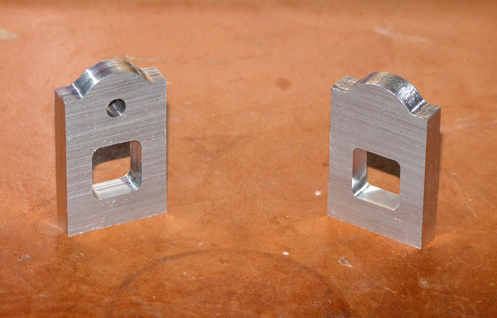
I was thinking about fixturing on the commute in to work today. Something simple that would make it easy to locate the key items, maximize the opportunity for any symmetry on setups, and simplify the rounding over on top. Here is what I have so far:
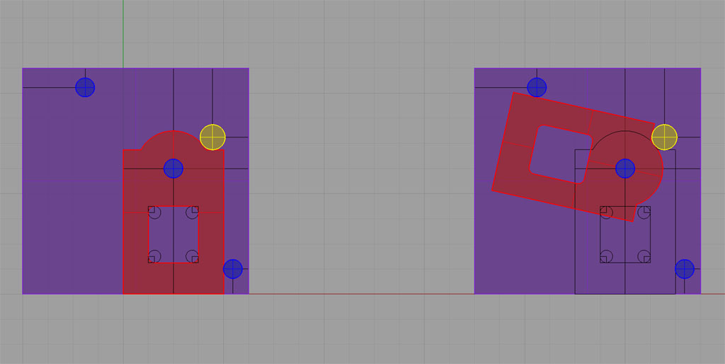
The fixture is just a base plate with 3 dowel pins, each 3/16" diameter. One is used as a pivot for the bearing hole. The other two are locater pins. You can see from the two how the rounding over works with the pins. I would envision making up a simple handle that bolts to the mounting bolt holes on the bottom of the part.
Manufacturing the part would go something like this:
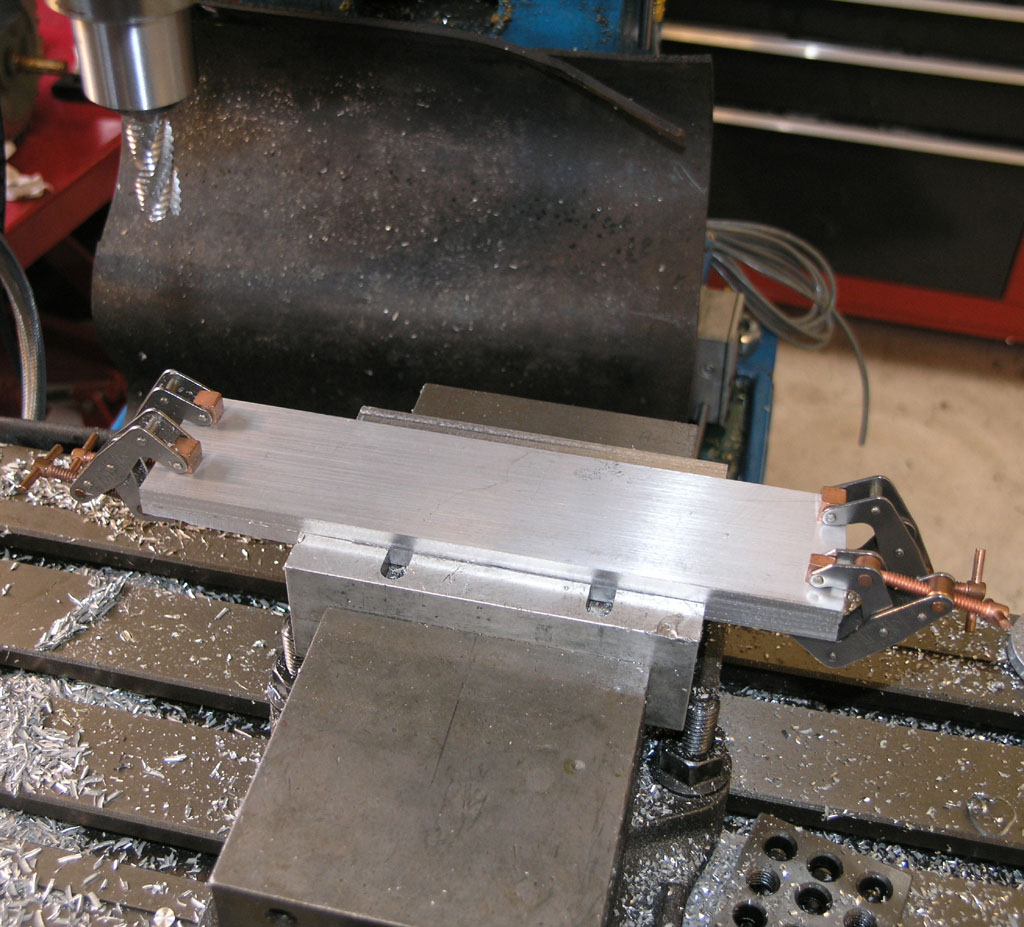
1. Square the blocks to proper dimensions.
2. Drill and thread the mounting holes in the bottoms. I'm envisioning using the Kurt vise with a vise stop so I can locate one hole and simple flip the part 180 degrees against the stop to get the other hole. This will make whipping through all 16 holes with threading fast.
3. Locate, drill, and ream the bearing hole. Another vise stop situation where you locate once for the first block and then the rest just drop into vise aligned with the vise stop.
4. Place the fixture plate in the Kurt vise. Drop the part on the pivot pin and locate against the lower right pin.
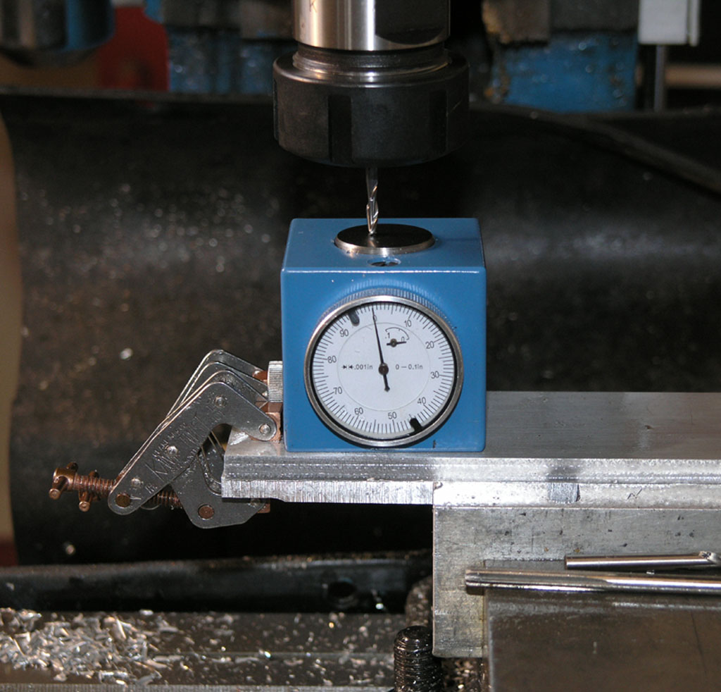
5. Locate the milling cutter to begin the cut with edgefinder, handwheels and/or DRO. BTW, the milling cutter is the yellow object in the CAD drawing. I'm assume a 1/4" diameter end mill in the drawing.
6. Begin the cut feeding very slowly with the part clamped. Monitor the DRO or handwheels. Even a single X-axis DRO is helpful here.
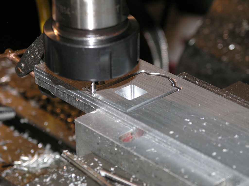
7. Unclamp and do the rounding over until we're against the top left pin.
8. Return the mill table to position, flip the part, and cut the other side while aligned against the lower right pin.
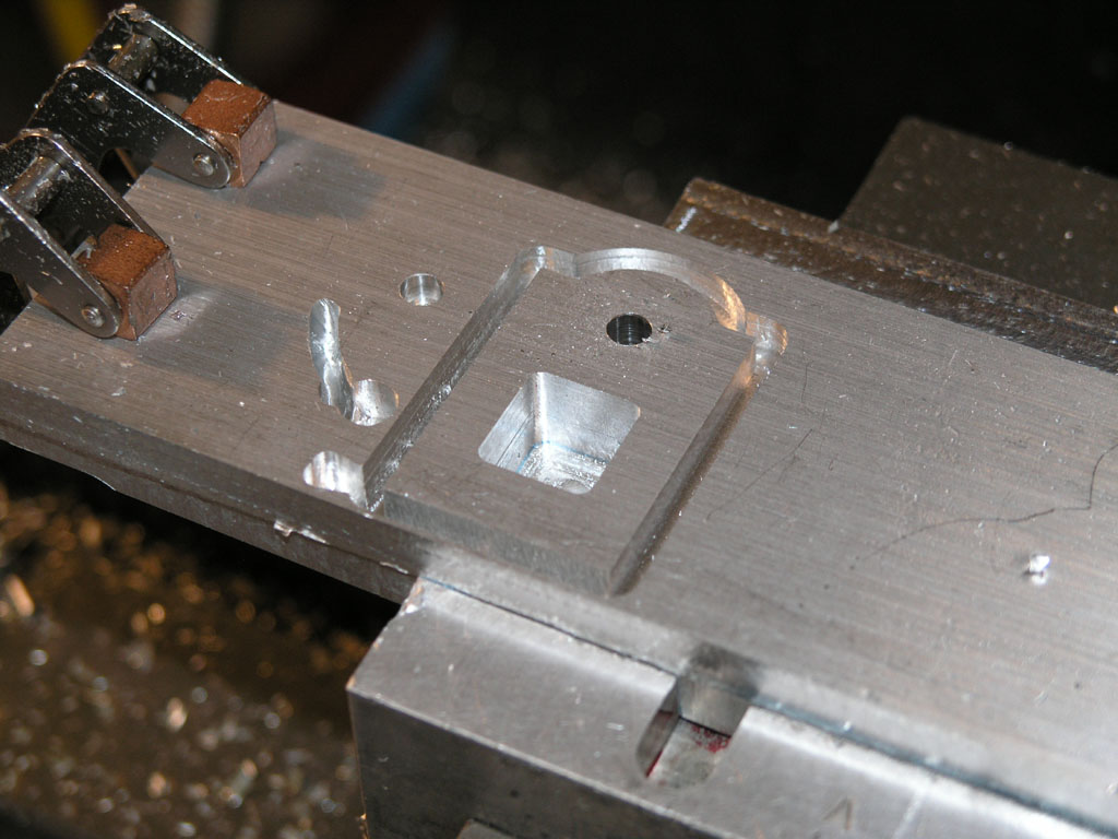
Last stage is to cut the "window" at the bottom:
1. Drill 4 corners. We can use this same fixture with clamping and flipping so we only have to locate top and bottom hole and flip the part to get left and right.
2. Use the fixture to mill out the window by connecting the corner holes. I've assume a 1/8" diameter end mill in the drawings.
What does everyone think of this approach? The fixture plate should be real easy to build and should save a fair amount of time. Others may want to play with the rotab. I have one, but felt this was faster/easier/more repeatable for 8 parts.
Cheers,
BW
The fixture is just a base plate with 3 dowel pins, each 3/16" diameter. One is used as a pivot for the bearing hole. The other two are locater pins. You can see from the two how the rounding over works with the pins. I would envision making up a simple handle that bolts to the mounting bolt holes on the bottom of the part.
Manufacturing the part would go something like this:
1. Square the blocks to proper dimensions.
2. Drill and thread the mounting holes in the bottoms. I'm envisioning using the Kurt vise with a vise stop so I can locate one hole and simple flip the part 180 degrees against the stop to get the other hole. This will make whipping through all 16 holes with threading fast.
3. Locate, drill, and ream the bearing hole. Another vise stop situation where you locate once for the first block and then the rest just drop into vise aligned with the vise stop.
4. Place the fixture plate in the Kurt vise. Drop the part on the pivot pin and locate against the lower right pin.
5. Locate the milling cutter to begin the cut with edgefinder, handwheels and/or DRO. BTW, the milling cutter is the yellow object in the CAD drawing. I'm assume a 1/4" diameter end mill in the drawing.
6. Begin the cut feeding very slowly with the part clamped. Monitor the DRO or handwheels. Even a single X-axis DRO is helpful here.
7. Unclamp and do the rounding over until we're against the top left pin.
8. Return the mill table to position, flip the part, and cut the other side while aligned against the lower right pin.
Last stage is to cut the "window" at the bottom:
1. Drill 4 corners. We can use this same fixture with clamping and flipping so we only have to locate top and bottom hole and flip the part to get left and right.
2. Use the fixture to mill out the window by connecting the corner holes. I've assume a 1/8" diameter end mill in the drawings.
What does everyone think of this approach? The fixture plate should be real easy to build and should save a fair amount of time. Others may want to play with the rotab. I have one, but felt this was faster/easier/more repeatable for 8 parts.
Cheers,
BW
 ) I'd go straight for the Rotary Table Myself. But like they say. "There's more than one way to skin a cat"