Stuart triple expansion steam engine.

Home Model Engine Machinist Forum

Help Support Home Model Engine Machinist Forum:

This site may earn a commission from merchant affiliate links, including eBay, Amazon, and others.
S

sanddancer

Guest
Good afternoon all,

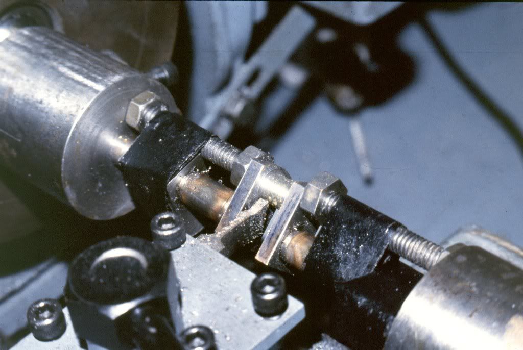
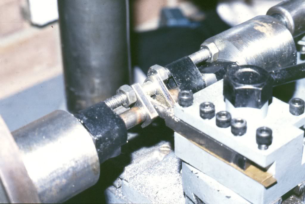
I have finally received my Stuart kit for the above engine, but not directly from Stuarts. Whilst awaiting delivery I did some research, & noted the comments about the built up crankshaft. I am unsure whether to be pleased or disappointed, but my kit has a one piece blank, & Stuarts tell me that it must be about 20 years old, although the kit is still shrink wrapped, and all parts are present. I did a Stuart compound crankshaft from a one piece blank about 25 years ago, but now that I am faced with this one I can see a very, very steep learning curve, as it is considerably longer than the last one. I have copies of all the articles about construction, written in Model Engineer in 1995, but they deal with the newer, built up version. Soooo, does anyone have any pearls of wisdom on this one. All comments & advice will be appreciated,

regards,

George
 
George, that's a great project, you've months years and possibly decades of fun ahead ;D There are a number of things that'll challenge and the crankshaft is one of them....fortunately as others have proven none are insurmountable. i'd like to just double check what is meant by built up vs one piece, do you mean silver soldered fabrication vs one large dia bar? if so, I'd say celebrate.

Mine came with the silver soldered fabrication. I've found turning from a spindly silver solder thingy a disaster and i quickly pretzel-ed it. In starting from a solid bar there's enough material strength that by going in the right sequence you its not too bad

here's the pretzel

pretzlecrank.jpg


here's the one made from solid (excluding webs, they are added after)

finishedcrank.jpg


There's a specific order to follow.....

- using the mill and x/y coordinates drill 4 centres (journal and 3 pins) in each of the ends - centres being aligned to one another
- machine each of the pins
- as you machine each pin, place an acurately made spacer in gap - this is critical
- used duct tape around the journal to ensure the pin stays put (handy mans secret weapon)
- after the three pins are done, turn the long shaft dia next to the tailstock - tailstock provides decent support for this
- reverse the shaft and using a collet, chuck the shaft portion just turned. Since the greatest overhang is now inside the headstock, its a little more rigid to turn the center journals.

other notes,

I ground two parting tools as a left and right and knife tools - with an appropriate radius between journal and side. to pick up a cut as you change from L to R tools, use permanent marker. come in until the tool scraps off the marker but no metal. This is tricky stuff machining the pins, you have reach a long way in in a narrow restricted space with a flimsly set up - light cuts and patience is the order of the day. are after all turning is done, mill the offsets from round to flat

hope that helps

btw - did yours come with the cylinder drain cocks? always wondered if they were supposed to be part of it. mine came sealed as well but i'm less than convinced the faster set is correct - there is an odd collection of fasteners, in no way follows the list....like i'm almst done and there must be 50 extra ba studs and nuts yet there only a couple of the requried 7ba counter sunk screws ???
 
Hi McGyver,

there's a whole barrowful of info, for which I thank you. I will need to study this, & think about it, as I am not a machinist, only a simple, scissorgrinding engineer! This machine of mine is a chester combined lathe & vertical mill, with a 4 jaw chuck, so the machine should be capable of doing the job, but am I? I don't fully understand some of your info, but I was worried about turning the crank pins, particularly the centre one. I can offset the 4 jaw chuck, but how would I support the other end?
Yes, the kit came with 4 draincocks, so it looks complete, although I am reluctant to break the shrink wrapping before I need any part, as I did this on the compound I did 25 years ago, & am still looking for bits, so it is difficult to check completely. I agree with you about this being a monumental project, & I honestly doubt if I will ever complete the job. I intend to plan & think, whilst improving my skills on simpler tasks, but I value this contact, & may well need advice again if thats ok with you,

regards,

George
 
I'll bet sailors ran for the exits after hearing the salty diatribe that erupted mcgyvers lips shortly after "pretzeling"!

How I hate when those moments happen.

OTOH, the new "billet" crank is sure a beauty. Maybe it was meant to be?

Cheers,

BW
 
I have made a triple crank fron solid I should still have the jigs I am in the UK where are you?
If you are intrested I could find them or draw them up so that you could recreate them

678-TrippleCrankshaft.jpg
679-TrippleCrankshaft.jpg
985-Triple.jpg
992-Triple.jpg


Paul Boscott
 
BobWarfield said:
I'll bet sailors ran for the exits after hearing the salty diatribe that erupted mcgyvers lips shortly after "pretzeling"!

naw, just a slow shaking of the head and wonderment at 1) why don't i just watch sitcoms like normal people, and 2) is it too early to start drinking heavily. fortunately it happened too early in the process for the hollow sense of loss.

Paul, nice triple, way to go figureout how to work with the silver soldered version

 
Paul,

I would be interested in seeing more pictures and drawings of your jig.

Eric
 
Triple

Start of by turning the crankshaft as if you go undersize by a few thow you can adjust the bearings to match

To use the crank shaft jig

Drill centre holes in each end of the crankshaft

Put crankshaft between centres and turn down the two end shafts to 7/16 that is a good fit on the jig then fit the jigs to the shaft.

Line put back between the main centres using a point of a lathe tool set on the centre line position the outer marks on the jig with the centre of the lobes that will become the big ends and well tighten cut some bolts just short of the gap between the end of the lobe and the jig put a nut on and adjust to be a tight fit without distorting the shaft.

Wrape some tape around just in case (as although it has 360 deg to chose from it will come out straight at your face)

See pictures

I ground a tool to do each side of the web and used a parting tool to do the big end bearing diameter.

When you have turned all three big ends remove jig and turn mains down to the correct size thus removing the marks in the shaft from the heavy clamping screws.


set up the base casting so as to mill the slots that the main bearings fit into all in one go to make sure they are in line and the same depth. make the outside of the main bearings to be a good fit in the slots (and the jig) make the bars that hold the mains in to the base casting. mark the pairs and which is the drive side

set the jig on to the faceplate so that the centre of the bearing is the centre line of the lathe drill out the all bearings to - 1/16 then bore out bearings to the size of the mains from the crank shaft ( as they are set to be on the centre line they can be made to fit the shaft the do not have to all be the same size) use the handle to check for smooth rotation


Crankshaftjig1.jpg


Crankshaftjig2.jpg


Crankshaftjig3.jpg


Triplecrank.jpg


Mainbearingholder1.jpg


Turnningmains.jpg


Basecastingholder.jpg


Runningintriple.jpg
 
Nice work, that crankshaft looks like a tough one.
Alec Ryals
 

Latest posts

Back
Top