Spark plug build tutorial

Home Model Engine Machinist Forum

Help Support Home Model Engine Machinist Forum:

This site may earn a commission from merchant affiliate links, including eBay, Amazon, and others.

gbritnell

Project of the Month Winner!!!
Project of the Month Winner
Joined
Jul 16, 2007
Messages
2,993
Reaction score
1,061
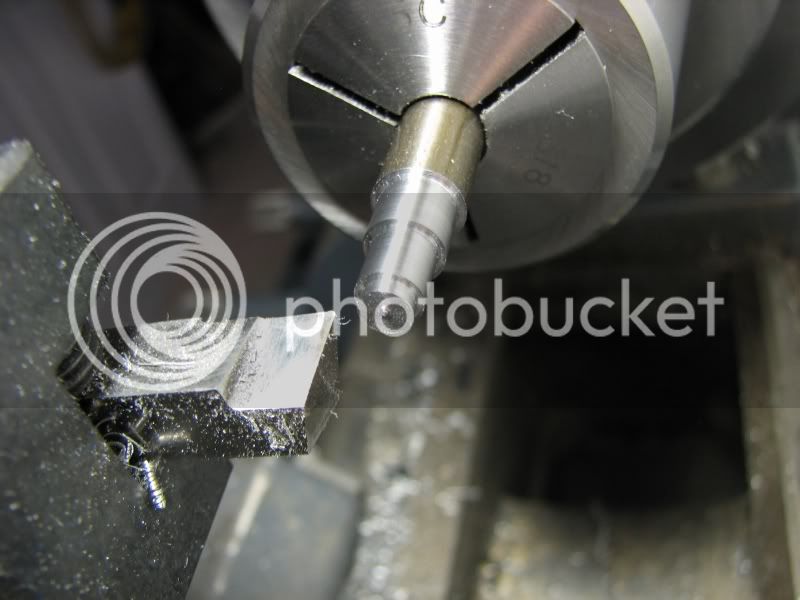
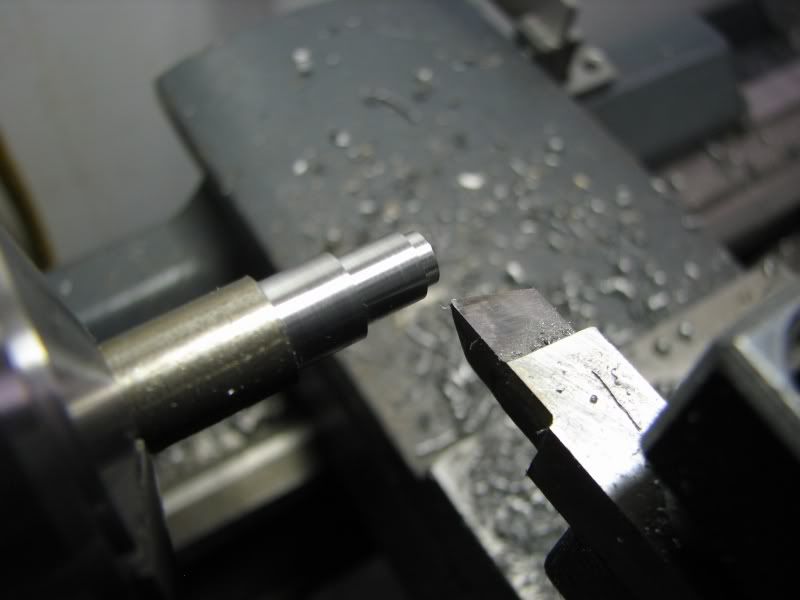
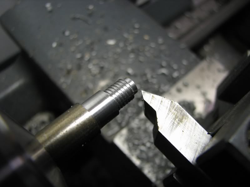
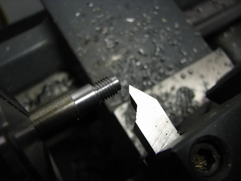
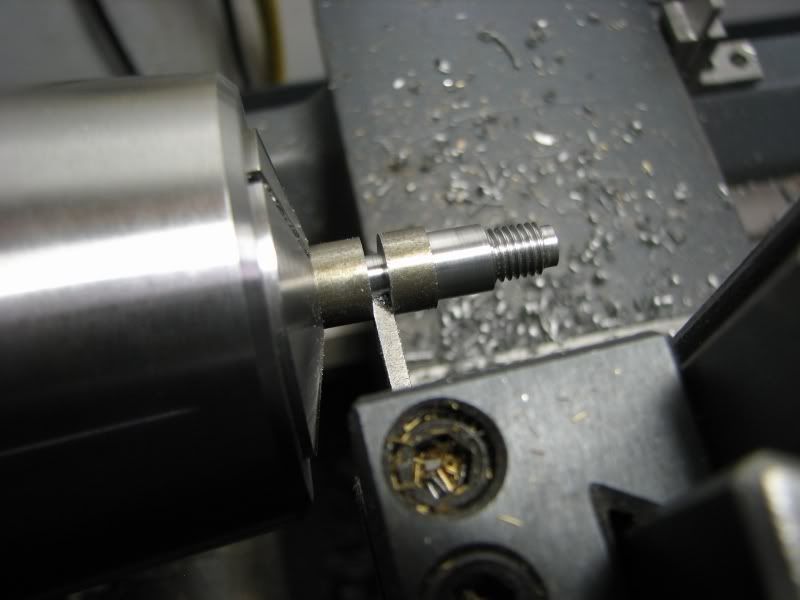
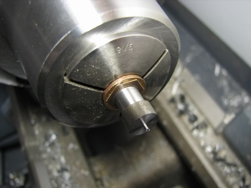
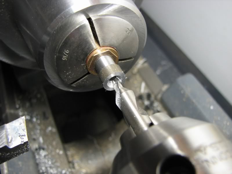
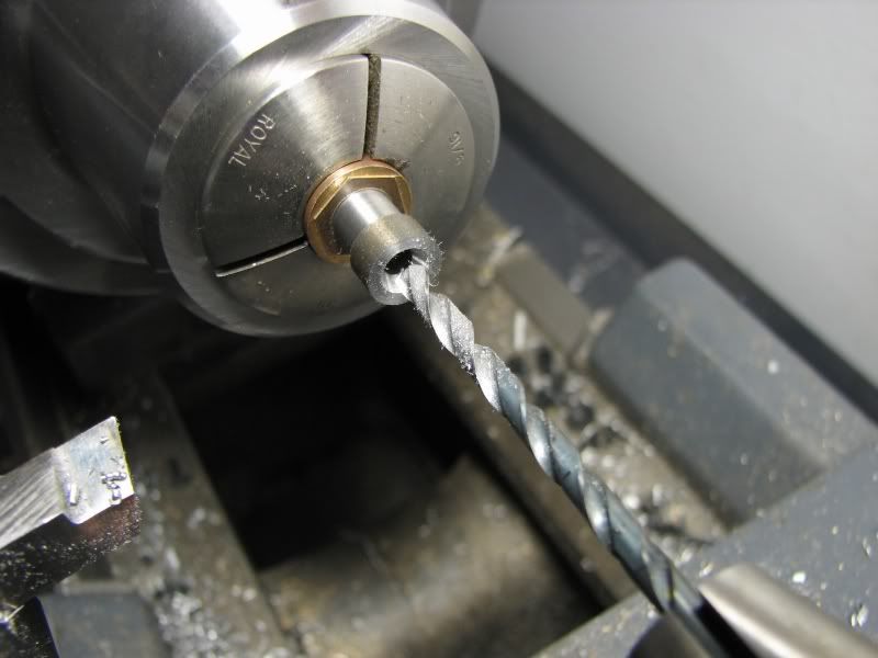
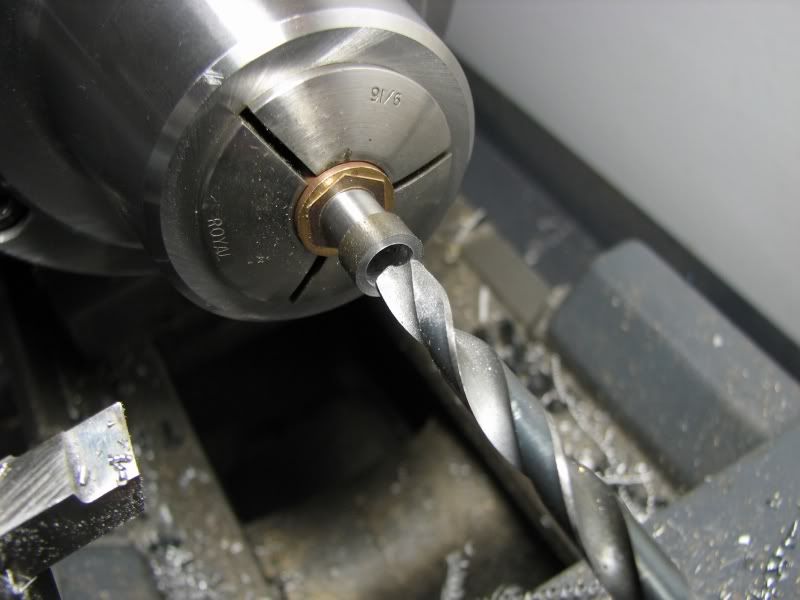
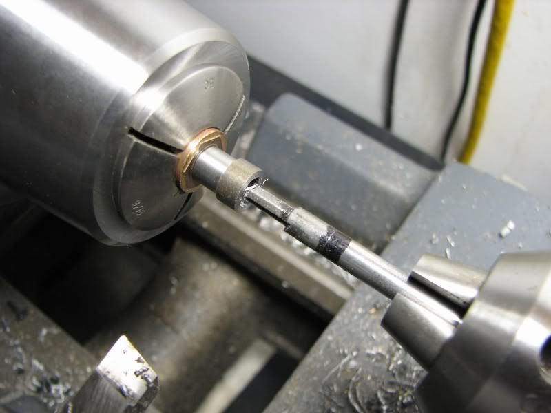
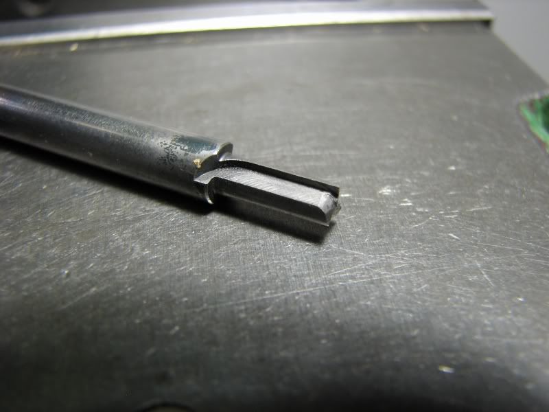
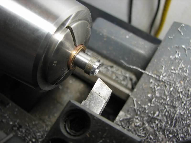
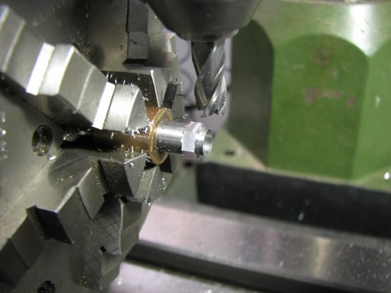
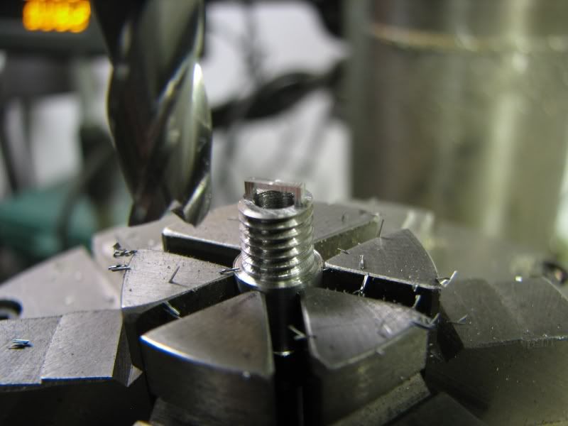
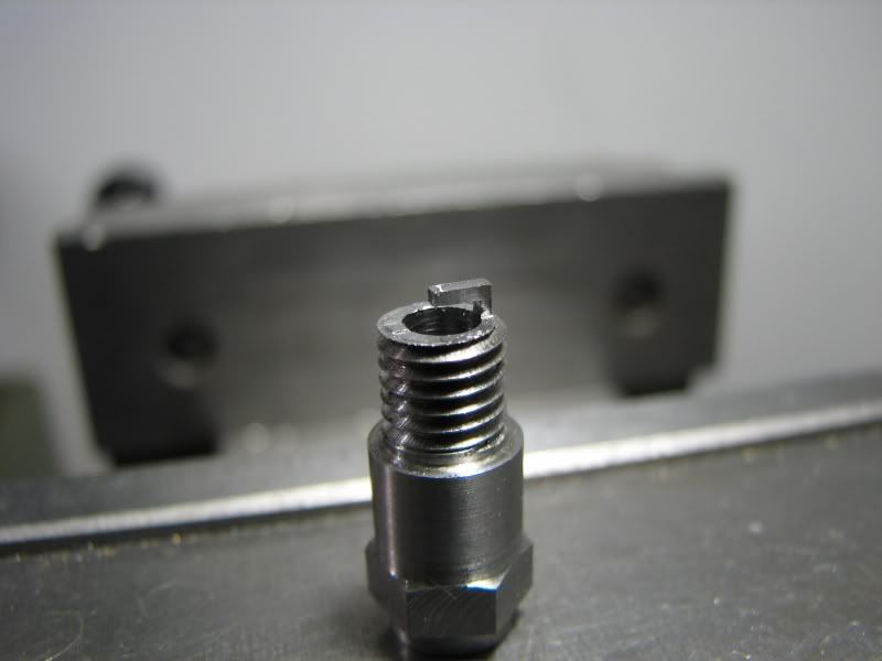
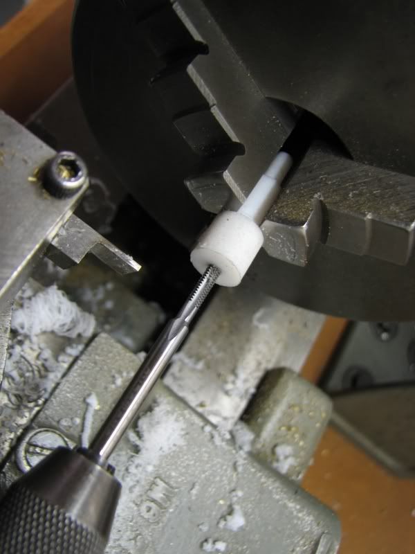
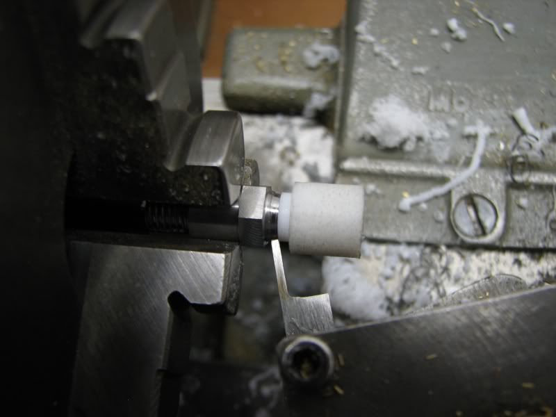
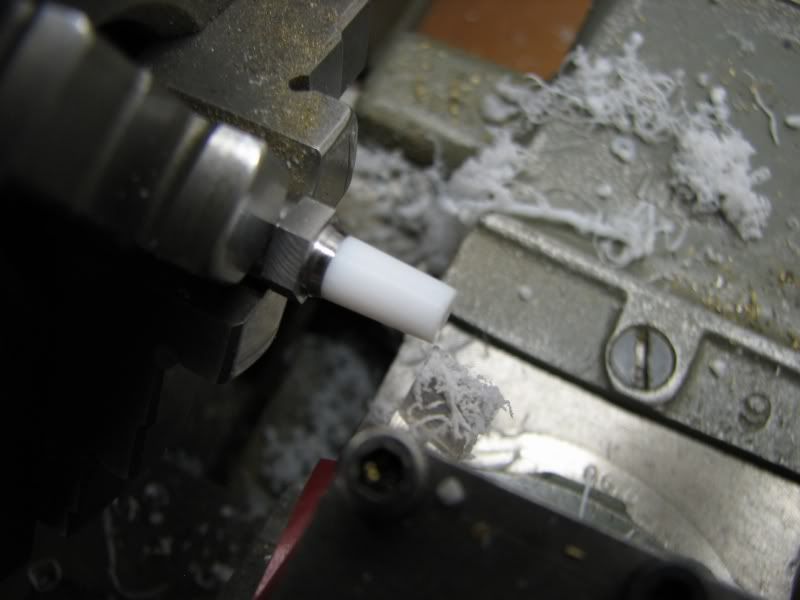
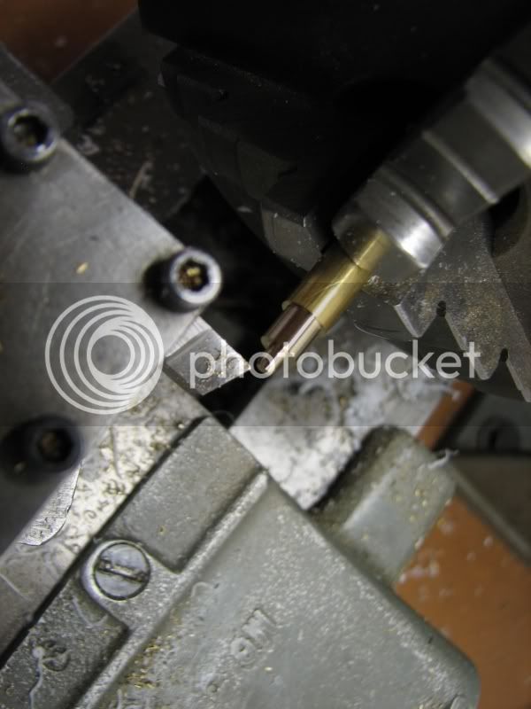
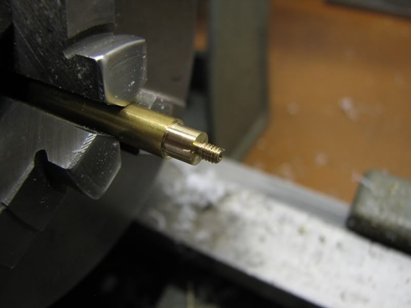
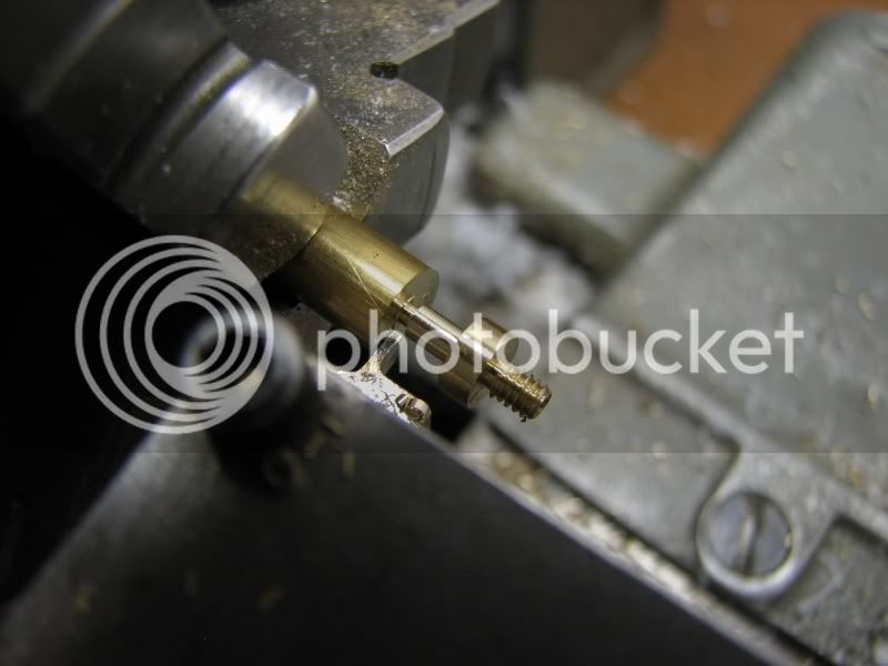
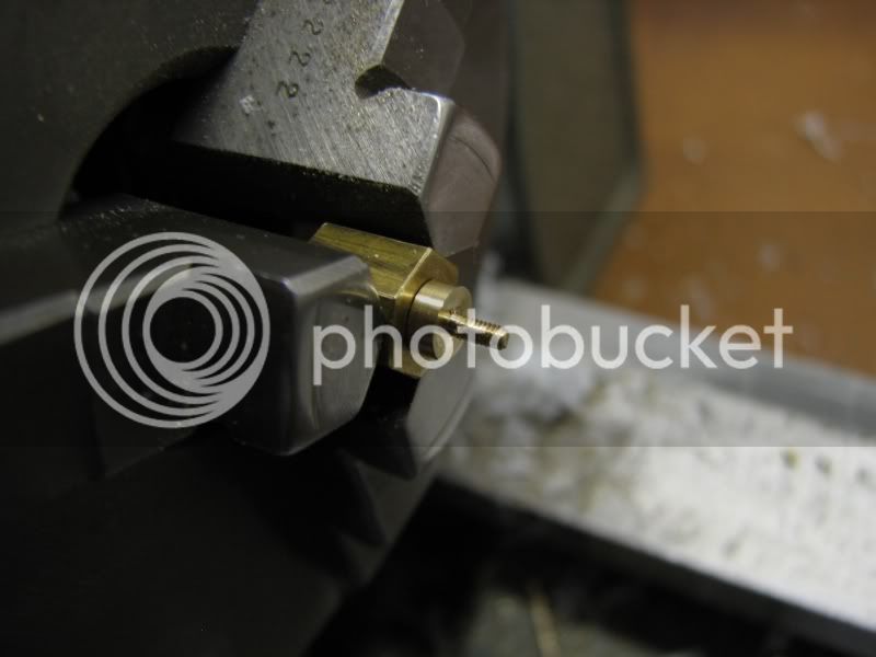
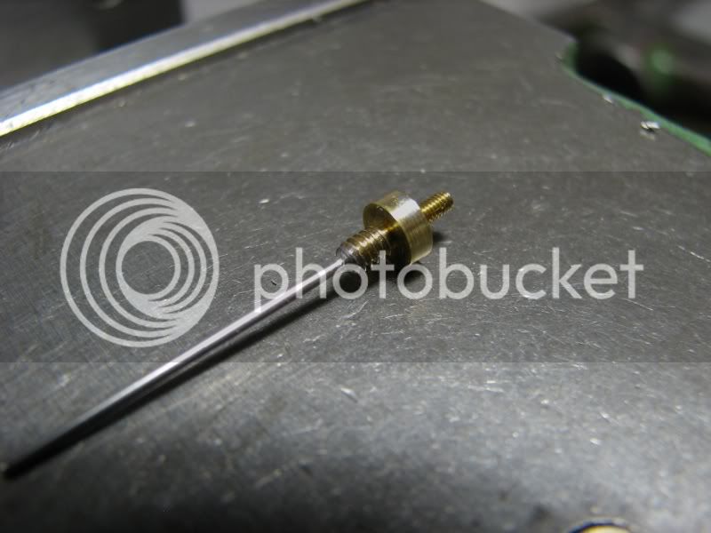
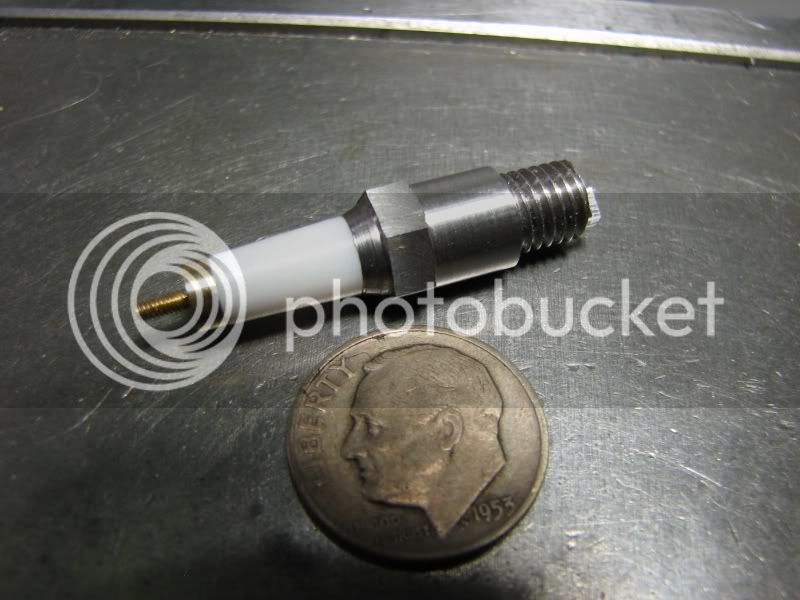
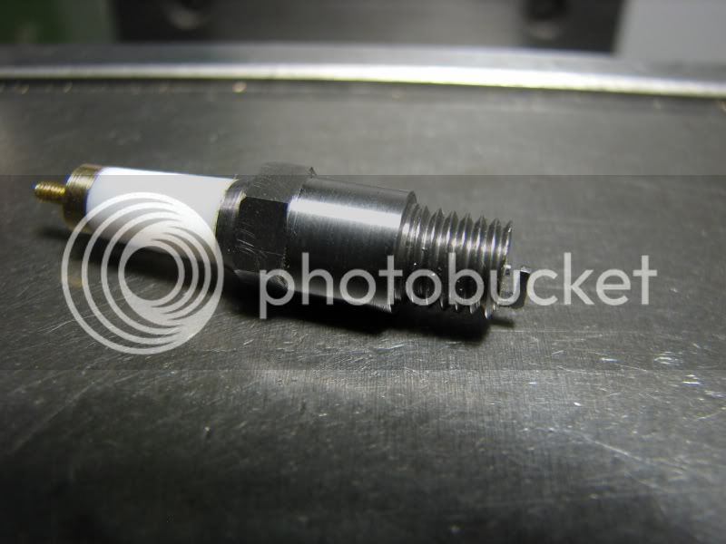
Good evening gentlemen. I am presenting my spark plug build tutorial for your edification. I have made a change to the manner in which I build them that differs a little from the drawing that I have posted in the downloads section. I have threaded the top of the insulator a short way and likewise the cap so that they screw together and can be removed to adjust for wear. To start off with I am using a piece of .375 dia. 12L14 steel for the body. The first series of photos shows the turning of the body, the first pass chasing the 1/4-28 thread, the finished thread and cutting off, leaving a little for facing when turned around for the next series of operations.

aturningbody1.jpg

bturningbody2.jpg

cthreadstart.jpg

dthreadfinish.jpg

epartingoff.jpg


You've certainly got MY attention George!

Rick
 
Ooo. I can tell this is gonna be good. Eagerly awaiting your next installment, G.B.

Dean
 
The next set of photos shows the part turned around in the lathe a screwed into a threaded bushing. The first operation is center drilling, then drilling with the small diameter drill. This drill is .147 dia. which leaves .025 metal wall between the root of the 1/4-28 thread. I don't drill through but stop short enough so that my next tool will square up the bottom of the pocket to form the inside shape of the electode. At this point you are asking "why 1/4-28 thread?" These are for my 302 Ford v8 which was built before commercial plugs were available and I felt that this thread size would be fine for what I needed. The next step is drilling the body diameter, .257. This leaves a .027 wall between the O.D. which is .312. Now I go in with a tool I made from drill rod and hardened it. It is .146 dia. and has 3 flutes. It's sharpened with a flat bottom. The depth is calculated to give me a .025 thick ground strap.
Finally in this set I turn the crimping band to have an .008 wall by .07 long.
fmountinfixture.jpg

gcenterdrill.jpg

hsmalldrill.jpg

jbodydrill.jpg

kbottomspface.jpg

kkspfacetool.jpg

lcrimpband.jpg


I would say "I'm all ears" but as I have to read it I guess I have to say "I'm all eyes"! :big: :big: :big: :big:

Ron
 
Now it's out of the lathe and over to the mill. The threaded bushing is clamped into my dividing head and the plug body is screwed in place. The hex is .312. The .375 round stock gives ample material to cut complete flats. I have a set tru chuck on my dividing head so I indicate the first plug body to get everything running true and each plug after that is pretty darn close. After all the hexes are cut I rotate the dividing head vertically to cut the sides of the ground strap. At this point you will see the square bottom left by the counterboring tool. The width of the strap is about .035. The last picture in this set show the ground strap cut off and filed to size. I use a jewelers saw on the one side first and then snip the remainder off with a small pair of cutters. The reason for sawing first is that if you snip it first it will bend the strap because the snipper jaws push out against the stock.
mmachinehex.jpg

nmachineelectrode.jpg

ofinishelectrode.jpg


George,
The suspense is killing me :bow:

Thanks for living up to your motto Thm: (Talent unshared is talent wasted.)

Enjoying it, can't wait for the next installment!
Tony
 
The body is now done except for some light filing, my Enco mill doesn't leave the smoothest of cuts. Now we move on to the insulator. Over the years I have talked to many builders and each one has his own material preference. Someone told me about Teflon ,Virgin Teflon. Apparently there are 2 grades, electrical and mechanical. Some fellows use Corian, the material used for sinktops and I also ran into a gent who used machineable ceramic. He had access to it in his job so that's what he used. I looked it up at our local supplier but it was a little pricey for me. I have had good luck with Teflon. The video of my 4 cylinder OHV engine running has Teflon plugs in it. I start out with a piece of .375 dia. I use this because the larger diameter gives me the ridgidity while machining. The first step is drilling for the center electrode. In this case I have some .039 straight music wire so I drill it with an .039 drill. I center drill it with a #00 center drill just enough to dimple it to get the drill started on center. I slide the tailstock back and forth in a pecking action to drill the Teflon. After this I turn the small diameter, .147, to the required length. I progessively work back on the stock with each diameter so that I have the stiffness of the stock to keep everthing concentric. Once my diameters are finished i use my turning tool to cut a small chamfer into the large diameter. This will be where the crimping band on the body will be swaged over to hold the insulator in place. At this point the piece of Teflon is cut off leaving a little for cleanup when mounted into the plug body. I show a picture of tapping the opposite side while holding the blank in my chuck. I only did this on the first insulator but subsequently mounted the insulator into the body and then tapped the hole. It's 3-48 thread. You just have to tap very lightly otherwise you'll just cut all the threads out when you hit bottom. I went about .187 deep.
pturntefloninsulator.jpg

qtapteflon.jpg

rcrimpinsulator.jpg


I got ahead of myself on the last picture. This shows the crimping (swaging) operation. I turn my cutoff tool so the tip matches the angle that I cut into the Teflon with my turning tool. I then run the tip of the tool up against the crimping band and start turning the lathe by hand, BACKWARDS!!! As I'm turning the spindle I slowly feed the cutoff tool in and after a couple of revolutions I check to see if the insulator is getting snug. I stop crimping when the insulator can't be turned by hand. There's no need to overdo it. It only has to be tight enough to do the finish turning on the diameter. I calculated the angle and set my compound over accordingly. I take light cuts, about .03, till I get to the diameter I want. In this case it's about .230. Once I'm at my finished diameter and up to the edge of the crimping band I just turn the compound out to make my finish cut. About 2.25 degrees.
staperoninsulator.jpg


Now it's on to the cap and center electode. I turn and thread the 3-48 thread first. This gives me a stronger thread to hold when I'm cutting the 0-80 thread on the other side. The length of the 3-48 thread is about .15. I also drill the .039 hole for the electrode about .125 deep. The thickness of the shoulder is arbitrary, mine is about .078. The part is cut off, turned around and screwed into another threaded bushing. Now the 0-80 thread is cut, with a die. I made a little knurled die holder to use by hand. I just put my center up against it and then turn it by hand. You have much more feel that way.
tturningcap.jpg

uthreadingcap.jpg

vsmalldieholder.jpg

wcapthread.jpg

xcutoffcap.jpg

y080thread.jpg


We're getting close now!! The next step is to cut a piece of piano wire, leaving it a little long, and insert it into the cap. I use 50-50 solder on it. I flux it up, press my soldering gun down against the cap and when the flux bubbles I touch it with a piece of solder. A little bit of solder ran into the lead thread so I just took it and screwed it into the die to clean it up. I now took the electrode to the bench grinder and adjusted the length. Go slowly or you'll have to unsolder the wire and slide it out. I made the depth about .125 for this very reason, not because I ground too much off but as the electrode wears I can unscrew it and adjust the length. After you're done grinding the end take a fine stone and break the edge otherwise you'll broach the hole in the Teflon bigger. I now grabbed the brass cap with my small chuck and pressed the electrode into the insulator. As I got to the threads I slowly turned the cap and screwed it in place. Don't overtighten it. Once it runs up against the shoulder of the insulator STOP!!! It's not going to go anywhere. Well boys and girls that does it for this WIP. I hope it helped out the fellows who've never done this before. The dimensions I gave along the way are what suited my needs. You can make them any size you need. I have some of these down to 6-32 thread and they work fine. The insulator erodes a little over time but they still function quite well.
gbritnell
zelectrodeandcap.jpg

zzplug1.jpg

zzzplug2.jpg


I love this stuff! Thanks a LOT for the great how-to article and photos.

Dean
 
+1.
I love these how to's with pics!
we MUST sticky this or make a section with locked threads so they never get covered over time.
 
What a great thread, thank you for sharing this. :bow:
 
George,
Excellent tutorial...makes me want to make a spark plug just because now I think I can. Thanks for sharing your experience.
Dennis
 
George, that was great! Thanks for sharing your skills and knowledge with us.
Mel
 
very interesting thread, thanks for sharing :bow:

 
Gbritnell, Excellent How-To Sir ! :bow:
Thanks very much for sharing!
Regards, Arnold
 
Back
Top