


arnoldb
Well-Known Member
- Joined
- Apr 8, 2009
- Messages
- 1,792
- Reaction score
- 12
I've really been enjoying the new milling machine I bought in February, but with an engine build done using it, some small nigglies appeared. These were not unexpected, but do need some attention.
I've been keeping a list of notes on "enhancements and adjustments" I'd like to make to the machine and it's accessories, and before I start a new build some of these are going to get attended to.
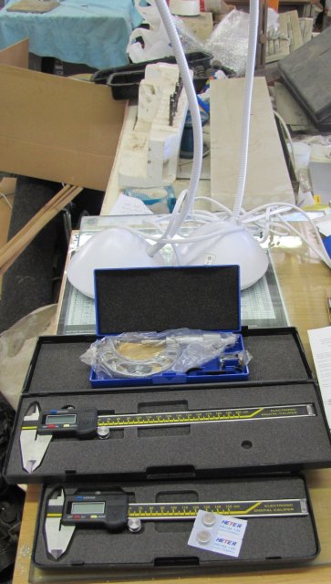
Yesterday morning, I went on some retail therapy, and came home with this lot, much to the chagrin of my bank manager;
2 digital calipers from the shop where I bought the mill, a "new" second hand 25-50mm micrometer (the price was right; I just could not resist!) and partly visible in the photo, the bases of two goose neck 12V 20W halogen "desk lamps":
One thing that's been bugging me about the mill is the fact that I have to switch it off at the power socket for it to be "off" - it has a transformer in its control box that is always on unless this is done. The power socket is behind the mill and a bit awkward to reach since I've added a table next to the machine to carry accessories. Also, it does not have an indicator that it is "on", and I've forgotten to switch it off a couple of times at the power socket. With lighting also an issue, I decided to dump these problems into the same box for solving.
I had an old "electronics project box" lying around from my student days, and a forage in the electrical boxes turned up a lights switch with three switches and more-than-adequate current ratings. I disassembled one of the lamps I bought, and installed its transformer in the box, as well as modified the lights switch to fit the box, and added an LED with required resistors to it. With some wiring, I ended up with this:
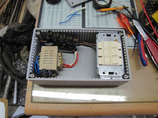
The goose neck and head salvaged from the light was mounted on the box cover, as well as a cut-out for the switches. The lot was then assembled and mounted on the mill's electrical box with short self tapping screws. I re-wired the mill to get it's electrical supply from the box, as the one switch in it now became the "Master" switch. The LED gives me a clear indication that the machine is on. The second switch controls the light; sometimes one might want it off even though the mill is on:
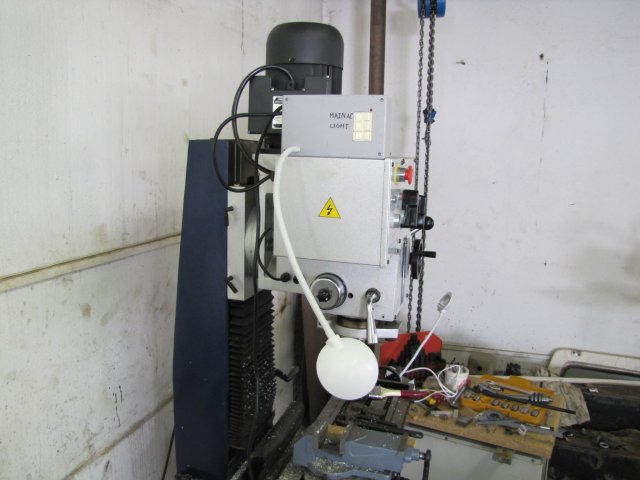
It's nice to have some additional light on the mill table:
I've not adjusted the mill's backlash since I got it, and it had quite a bit - about 1mm on both X and Y. Fortunately it has adjustment screws; they are just hard to get to.
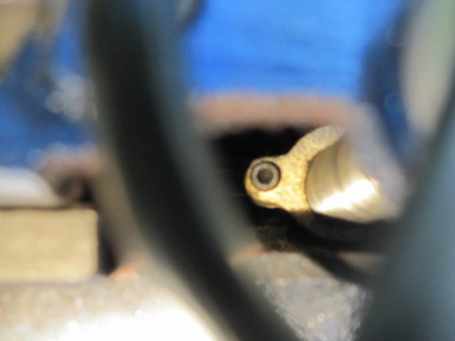
Here is a view of the X feednut and adjustment screw; I had to use a torch and the camera at the same time, so the photo is not that good. The black fuzzy arc in the foreground is the handwheel:
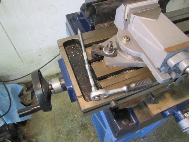
The previous photo is a bit deceptive; it makes the feed nut look close. In fact, I had to use the long and short extensions from my 6mm socket set with a 4mm hex bit to reach it for adjusting:
Fortunately, I left the stand I built for the mill open in the center; that makes getting to the Y feednut and adjustment screw easier. A view from the floor to the base of the mill:
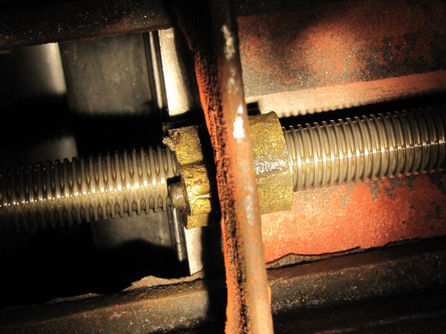
This is where I love the swivel view panel on my camera, I could get a photo without crawling under the mill! Makes inspection easy as well; a lot of rust showing up that needs addressing!
Both the X and Y adjustment screws were adjusted to the point where I could feel the feed tighten up(screw too tight), and just a bit back. All in all , the backlash came down from ~1mm to 0.2mm, and that's just dandy with me. Both feeds were feeling a bit "spongy" when changing direction, but are now nice and crisp.
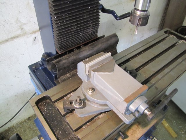
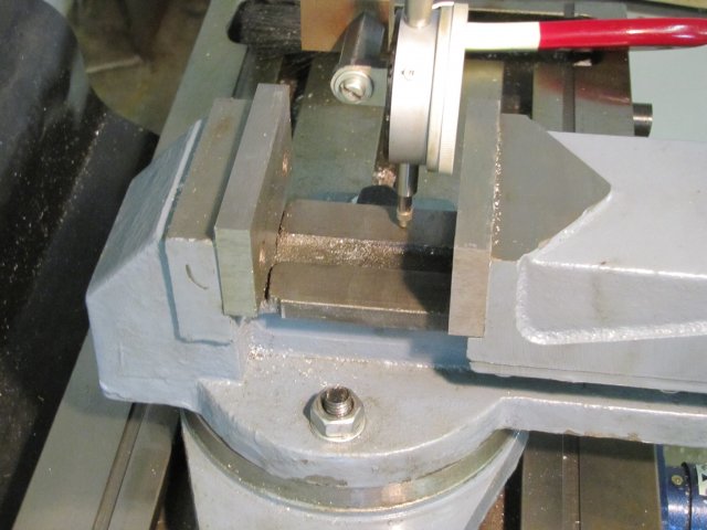
The next mod is (was) to the mill vise; I bought what I could find and afford when I bought the vise, which is an Asian import that is of rather poor quality-of-finish. It was either that, or nothing (until I can make my own). The next photo shows how I "shimmed" it to prevent the movable head rising ~1mm when tightening with parts in the top of the vise. I just measured the gap between the bottom guides and the vise body, and added plate strips of suitable thickness bent at both ends to prevent them from moving out:
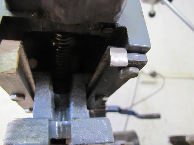
Actually, I made this change while building my last engine. It's a bit of a bodge, and by no means very tidy, but has brought the jaw lift down to less than 0.01mm.
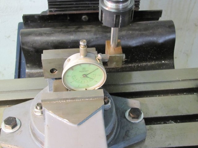
Today, after eventually re-mounting the vise on the right-hand side of the mill table, I checked its bed for "parallelism" to the mill table. I was expecting the worst, but was nicely surprised. In both the X and Y directions I measured, it was less than 0.005mm out according to my trusty Mitutoyo gauge. Two photos of the set-up I used to check:
On close inspection of the vise mods, I found this:
The movable jaw top is nearly 1mm lower than the fixed jaw top. A quick test with a file on the jaws, and they are pretty hard; I won't be trying out any of my HSS end mills or flycutter to correct this. I don't have access to a surface grinder to correct it either. So I'll be making up some "soft jaws" for the vise; and keep the originals for non-precision work.
More mods to come...
Regards, Arnold
I've been keeping a list of notes on "enhancements and adjustments" I'd like to make to the machine and it's accessories, and before I start a new build some of these are going to get attended to.
Yesterday morning, I went on some retail therapy, and came home with this lot, much to the chagrin of my bank manager;
2 digital calipers from the shop where I bought the mill, a "new" second hand 25-50mm micrometer (the price was right; I just could not resist!) and partly visible in the photo, the bases of two goose neck 12V 20W halogen "desk lamps":
One thing that's been bugging me about the mill is the fact that I have to switch it off at the power socket for it to be "off" - it has a transformer in its control box that is always on unless this is done. The power socket is behind the mill and a bit awkward to reach since I've added a table next to the machine to carry accessories. Also, it does not have an indicator that it is "on", and I've forgotten to switch it off a couple of times at the power socket. With lighting also an issue, I decided to dump these problems into the same box for solving.
I had an old "electronics project box" lying around from my student days, and a forage in the electrical boxes turned up a lights switch with three switches and more-than-adequate current ratings. I disassembled one of the lamps I bought, and installed its transformer in the box, as well as modified the lights switch to fit the box, and added an LED with required resistors to it. With some wiring, I ended up with this:
The goose neck and head salvaged from the light was mounted on the box cover, as well as a cut-out for the switches. The lot was then assembled and mounted on the mill's electrical box with short self tapping screws. I re-wired the mill to get it's electrical supply from the box, as the one switch in it now became the "Master" switch. The LED gives me a clear indication that the machine is on. The second switch controls the light; sometimes one might want it off even though the mill is on:
It's nice to have some additional light on the mill table:
I've not adjusted the mill's backlash since I got it, and it had quite a bit - about 1mm on both X and Y. Fortunately it has adjustment screws; they are just hard to get to.
Here is a view of the X feednut and adjustment screw; I had to use a torch and the camera at the same time, so the photo is not that good. The black fuzzy arc in the foreground is the handwheel:
The previous photo is a bit deceptive; it makes the feed nut look close. In fact, I had to use the long and short extensions from my 6mm socket set with a 4mm hex bit to reach it for adjusting:
Fortunately, I left the stand I built for the mill open in the center; that makes getting to the Y feednut and adjustment screw easier. A view from the floor to the base of the mill:
This is where I love the swivel view panel on my camera, I could get a photo without crawling under the mill! Makes inspection easy as well; a lot of rust showing up that needs addressing!
Both the X and Y adjustment screws were adjusted to the point where I could feel the feed tighten up(screw too tight), and just a bit back. All in all , the backlash came down from ~1mm to 0.2mm, and that's just dandy with me. Both feeds were feeling a bit "spongy" when changing direction, but are now nice and crisp.
The next mod is (was) to the mill vise; I bought what I could find and afford when I bought the vise, which is an Asian import that is of rather poor quality-of-finish. It was either that, or nothing (until I can make my own). The next photo shows how I "shimmed" it to prevent the movable head rising ~1mm when tightening with parts in the top of the vise. I just measured the gap between the bottom guides and the vise body, and added plate strips of suitable thickness bent at both ends to prevent them from moving out:
Actually, I made this change while building my last engine. It's a bit of a bodge, and by no means very tidy, but has brought the jaw lift down to less than 0.01mm.
Today, after eventually re-mounting the vise on the right-hand side of the mill table, I checked its bed for "parallelism" to the mill table. I was expecting the worst, but was nicely surprised. In both the X and Y directions I measured, it was less than 0.005mm out according to my trusty Mitutoyo gauge. Two photos of the set-up I used to check:
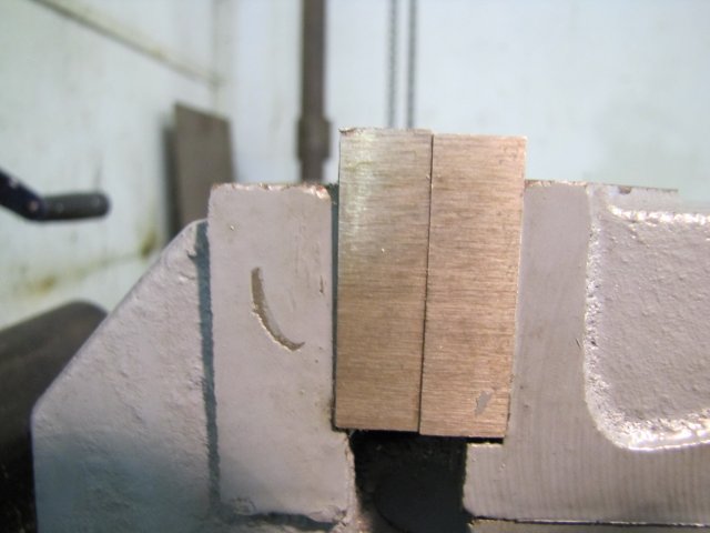
On close inspection of the vise mods, I found this:
The movable jaw top is nearly 1mm lower than the fixed jaw top. A quick test with a file on the jaws, and they are pretty hard; I won't be trying out any of my HSS end mills or flycutter to correct this. I don't have access to a surface grinder to correct it either. So I'll be making up some "soft jaws" for the vise; and keep the originals for non-precision work.
More mods to come...
Regards, Arnold