deere_x475guy
Well-Known Member
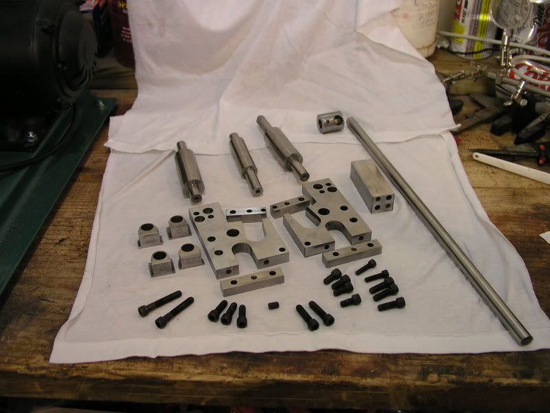
Thought I would share this with everyone. This is a ring roller I built a year ago or so. The basic plans are from the Model Engineer magazine and I used Corel Draw to rearrange the holes so I could use the stock I had on hand.
Here's a pic of all the parts laid out:
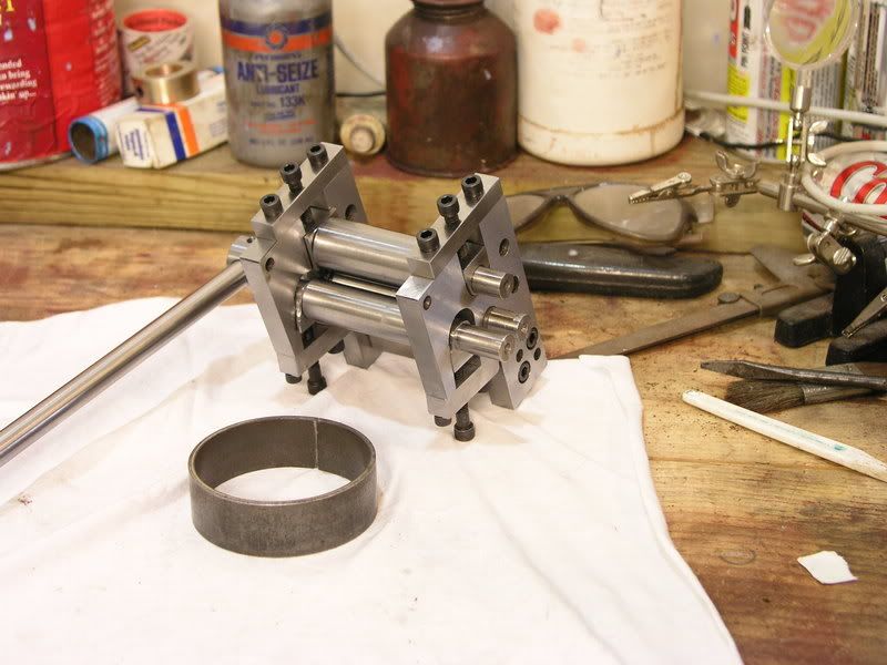
Here it is all assembled with a ring I rolled out of 1/8" stock. This is the absolute heaviest stuff I would ever want to roll with this little guy.
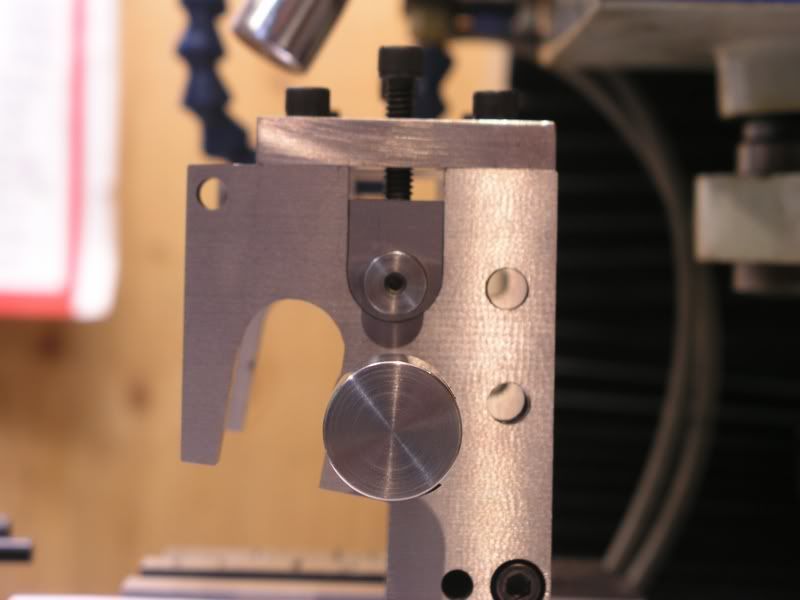
I wasn't real happy with the radius I got with the first set of bearing blocks so I used one of Marv's programs (rounder) and cut it on the mill with a 1/2" ball end mill. This is what the fit looked like when I was done.
Here is a sample out put from Marv's "Rounder" program. I know there are other ways of doing this but I thought I would give this a try....and I needed to test out the new DRO ;D ;D
Workpiece radius = 0.500 in
Ball mill diameter = 0.500 in
A = (R+r)*sin(theta)
B = (R+r)*cos(theta)
C = (R+r)*(1 - sin(theta))
D = (R+r)*(1 - cos(theta))
ANGLE A B C D
0.0 0.000 0.750 0.750 0.000
5.0 0.065 0.747 0.685 0.003
10.0 0.130 0.739 0.620 0.011
15.0 0.194 0.724 0.556 0.026
20.0 0.257 0.705 0.493 0.045
25.0 0.317 0.680 0.433 0.070
30.0 0.375 0.650 0.375 0.100
35.0 0.430 0.614 0.320 0.136
40.0 0.482 0.575 0.268 0.175
45.0 0.530 0.530 0.220 0.220
50.0 0.575 0.482 0.175 0.268
55.0 0.614 0.430 0.136 0.320
60.0 0.650 0.375 0.100 0.375
65.0 0.680 0.317 0.070 0.433
70.0 0.705 0.257 0.045 0.493
75.0 0.724 0.194 0.026 0.556
80.0 0.739 0.130 0.011 0.620
85.0 0.747 0.065 0.003 0.685
90.0 0.750 -0.000 0.000 0.750
Oh yea...almost forgot. The two empty holes you see are threaded for posts so I can add gears to this if I want to.
Here's a pic of all the parts laid out:
Here it is all assembled with a ring I rolled out of 1/8" stock. This is the absolute heaviest stuff I would ever want to roll with this little guy.
I wasn't real happy with the radius I got with the first set of bearing blocks so I used one of Marv's programs (rounder) and cut it on the mill with a 1/2" ball end mill. This is what the fit looked like when I was done.
Here is a sample out put from Marv's "Rounder" program. I know there are other ways of doing this but I thought I would give this a try....and I needed to test out the new DRO ;D ;D
Workpiece radius = 0.500 in
Ball mill diameter = 0.500 in
A = (R+r)*sin(theta)
B = (R+r)*cos(theta)
C = (R+r)*(1 - sin(theta))
D = (R+r)*(1 - cos(theta))
ANGLE A B C D
0.0 0.000 0.750 0.750 0.000
5.0 0.065 0.747 0.685 0.003
10.0 0.130 0.739 0.620 0.011
15.0 0.194 0.724 0.556 0.026
20.0 0.257 0.705 0.493 0.045
25.0 0.317 0.680 0.433 0.070
30.0 0.375 0.650 0.375 0.100
35.0 0.430 0.614 0.320 0.136
40.0 0.482 0.575 0.268 0.175
45.0 0.530 0.530 0.220 0.220
50.0 0.575 0.482 0.175 0.268
55.0 0.614 0.430 0.136 0.320
60.0 0.650 0.375 0.100 0.375
65.0 0.680 0.317 0.070 0.433
70.0 0.705 0.257 0.045 0.493
75.0 0.724 0.194 0.026 0.556
80.0 0.739 0.130 0.011 0.620
85.0 0.747 0.065 0.003 0.685
90.0 0.750 -0.000 0.000 0.750
Oh yea...almost forgot. The two empty holes you see are threaded for posts so I can add gears to this if I want to.
")