Simple minded engine ideas-everyone may post.

Home Model Engine Machinist Forum

Help Support Home Model Engine Machinist Forum:

This site may earn a commission from merchant affiliate links, including eBay, Amazon, and others.
wobbler motor working at the base of a triangle support for a flywheel. Make the triangle plate larger and put the flywheel in the middle and add two more wobbler pistons and...

trianglewobbler.gif


I've started making the parts list and drawings for the Vertical Osc. Engine. whose build instructions are already uploaded here as a pdf file.

I'll add the completed/updated parts list and drawings to the pdf files when I have a working model built.

a.gif


Lovingly, for those who give a hoot,
Kermit

Edit: added the pdf with the overall parts view, minus the gaskets and screws etc. More complete drawing made as I go.

View attachment Vert Osc 1 Cyl.pdf
 
More simple pictures that are of incredible importance to me.

more SIMPLE stuff from my simple mind,
Kermit :D

cutawaysteamengine.gif


cutawaysteamenginecloseup.gif


I'm getting ahead of myself,
Kermit


I'm designing the steam block for the oscillator and I'm not sure I can do "slots"

I am sure that round holes are possible. So....

untitled-3.gif


I'm thinking the one with holes would be the one I need to go for first time around and go for the slotted design when I get a mill.


thanks for letting me talk myself into it :)
Kermit
 
Your project is looking good so far Kermit. If you have Dremel style rotary tool available. you could use it with judicial usage to open out the drilled holes into the slots that you are thinking about. A very small diamond bit and a lot of patience are the needs of the day for that method as well as a steady hand. Of course the drilled passages would be fine in that application as well, and simpler too. Whichever method that you decide to go with, by all means keep us posted of your progress (or setbacks) as we can all learn from the experience.

Jim B.
 
Kermit,

When you have drilled the four holes, press fit a lump of brass into each and then you will be able to drill a third and sixth hole between them.

Hope that helps and makes sense. ??? ???

Best Regards
Bob
 
I know exactly what you are up to with the brass plugs - redrilling between them, but my lack of any true experience with these things prevents me from thinking of it. :mad: Something that is present-information I KNOW, but then can't bring forth with any presence of mind when presented with a problem calling for that solution.) Bah!

;D I'm hooked and I haven't made a chip yet!

So while I wait for paint to dry on my million dollar pedastal for a hunk of chinese iron :p I've been doing more 'figurin'

Some of you will get that :D


I have a finalized form and size for all the major pieces. The bore will be 1 inch and the stroke will be 2 1/2 inches. The flywheel will be 5 inches across. I'm starting to think some nice oak or hickory posts would work really well on the A frame.

So with the third version comes the final form. At least until I start making parts ;)

Hoot, hoot,
Kermit

View attachment Vert Osc 1 Cyl_REV_C.pdf

View attachment Steamchest detail_1.pdf
 
It's that time of the week for me to "reply" to my very own little thread. Then I get some popcorn and click the link and admire the work. Or something like that hey! ;D

Just another piece of the puzzle . The flywheel design decided on and drawing made. This time complete with a rotated 25 degree perspective view. Strange angle to choose but I'm trying to learn these things from books and don't have a teacher as such.

The Vert Osc 1 cyl plans have been upgraded as well; to Revision D now. :) Wonder where I'll be when I finally have a working first engine? ???

Why, right here of course. :D Silly question, no?

Kermit

View attachment Vert Osc 1 Cyl REV_D.pdf

View attachment Vert Osc_Parts_Flywheel.pdf
 
vertosc.gif


I'm only able to use Google SketchUp at work. The 3D model is progressing slowly while I learn 3D drafting.

I'm done, as you were!
Kermit
 
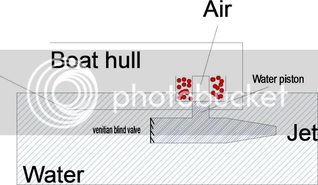
Thinking about Put Put boats the other day I got to thinking I wonder if it would work big scale?

then I made a connection between the V1 Ram jet and the put put idea - as below.

Stirlingram.jpg


The external heat source could be anything - charcoal for example. The air space heats up and expands, as the water in the "cylinder" is pushed below the waterline the air is in contact with and cooled by the river water and contracts - there may be some room here for a Stirling type displacer to improve the heat/cool effect.

More water is allowed to enter through a Venetian blind type valve at the front assisted by forward movement to repeat the cycle.

As an alternative I guess a flash boiler and spraying water in with a pump would be a simplier approach using the generated steam to create a jet at the back.

I guess try it and see if it works is the answer - could be interesting if your not looking for great speed but highly flexible fuel source.
 
That's a unique design. Wouldn't the tubing directions need to be more "in-line" with any thrust generated by the water flow?

As opposed to the ninety degree bend you have in the drawing?


Thanks for the addition to the thread Rick,
Kermit
 
The overall design would need refining - just trying to get the principle over with the diagram as I have no idea if it would work.

A displacer should be fairly easy to implement as well to improve the gas flow. It's really a liquid piston Stirling engine.
 
Kermit said:
While reading about pumping engines I found something about a "compensator cylinder". They were attached in pairs to a cross head and would offer resistance to the power stroke as it began. The resistance then reversed and the cylinders offer an acceleration to the end of the power stroke. This was supposed to provide economy and was also spoken of as a flywheel replacement. One could use much less massive flywheels, making a motor lighter thereby providing more power to farmers who used mobile engine platforms(authors suppositions)

The cylinders are connected to a larger chamber and thereby offer a constant pressure. Compression does not take place as would be supposed by the drawing. The pressure in the large chamber being adjusted to whatever value was wanted to ensure smooth running under load. The air was communicated to the inside of the rotating spindle on which the cylinder was suspended no valving needed. A pressure of say 100 psi could be used first to resist the power stroke, then to assist the power stroke near its end.

The idea being, I suppose, to even out the use of power - capture some early in the stroke and apply it later. For this to work at all, the cylinders would need to be double acting, otherwise the drag on the upstroke would probably stop the works. A double acting engine where steam is fed alternately to one end of the cylinder and then to the other end, might work with these.

For pressurizing the reservoir, assume a small air pump driven by the engine. With a diverter valve on the line, it could be decoupled when the desired pressure was reached.

Actually there will be compression cycles. The amount will be based on the total volume change, not just the volume change in the small cylinders. You might be able to get the same effect by using open cylinders and compression springs.

Alan
 
I've probably just re-invented the wheel here. I was troubled by thinking I had to get the distances just right so things would line up. I found however, that in this type of layout the valve is sized to the drilled through openings and then you just add a few percent more or less for your steam cutoff. One could just make his cylinder then drill his inlet and exhuast ports and after all that is done measure up the distances and turn up a valve cylinder to fit...

right????


untitled.gif
 
Kermit-

I'm new here, and if I had been around earlier, I would have mentioned this when you posted your initial drawings.

Pins running in slots have a very limited life under the conditions that exist in an engine- so the first thing that comes to mind is to use some sort of a rolling bearing on the pin. What few realize is that when the bearing is moving (lets say) up in the slot, loads are pushing it to one side of the slot, causing it to rotate. When it gets to the top, it reverses and starts down, but the loads push it to the other side of the slot- and make it rotate the other direction. While this works fine in slow speed operations (< 100 reversals per minute, depending on bearing mass and inertia) at even slow engine speed the bearing is not able to respond, and just skids, becoming, in effect, just a larger pin. Drawing this out roughly on paper will show you what I'm talking about. The usual way to resolve the problem is to use a block that slides in the slot, with the pin "rotating' in the center- look inside a metal shaper- you will see this arrangement.

Herb Kephart
 
ebtm3 said:
...use a block that slides in the slot, with the pin "rotating' in the center- look inside a metal shaper- you will see this arrangement.

Herb Kephart

So it needs to be arranged more like a cross head then. Thanks for the insights; I would have adopted the roller bearing idea and not have known about the cross forces distorting the race and locking up the bearing.

Does increasing the axial length of the bearing surface compensate for this effect or does the length of increase required to achieve stability render the bearing overly large?

Kermit
 
killing time with some idea drawings, since the miniature endmills in 3/32 and 5/64 didn't come by Fridays last delivery.

Just more adaptions to a single acting cylinder with piston valve, hopefully, designed so as to be easy(er) to machine. Easy being a relative term paired with experience.

Hope someone finds these useful

pistonvalve.gif


Kermit said:
Does increasing the axial length of the bearing surface compensate for this effect or does the length of increase required to achieve stability render the bearing overly large?

I was hoping to get an answer. The posters original information indicated he might know something about it. :-\ (shoulder shrug)

I'll go back to whatever I was doing before stopping to bother you nice people,
Kermit

View attachment drawing dated 8-29-09-a.pdf

View attachment drawing dated 8-29-09-a.pdf
 
Back
Top