Simple Jingle Bell Motor

Home Model Engine Machinist Forum

Help Support Home Model Engine Machinist Forum:

This site may earn a commission from merchant affiliate links, including eBay, Amazon, and others.

ke7hr

Active Member
Joined
Sep 9, 2009
Messages
42
Reaction score
2
Even with novice machinist skills, I have been wanting to build a motor for some time. I have looked as a myriad of plans and projects, finally settling on a simplified Jingle Bell Motor based on the one at
http://npmccabe.tripod.com/jinglebellmotor.htm

I downloaded a FREE 2D CAD program, DoubleCAD XT, and set about redrawing the motor in a simplified way to suit my totally manual "3 in 1" machine and my (hopefully) budding skills. I posted the simple plans in the download section of HMEM with permission.

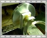
Today I got a chance to start cutting and making the motor. The frame seemed like the place to start. I cut the .500" thick aluminum a bit oversize to mill it to size.

SJBM_01_frame_milled_width.JPG


SJBM_02_frame_milled_length.JPG


<hr>

The step in the frame was then milled to size.

SJBM_04_frame_milled_step.JPG

<hr>

The hole locations were then laid out. I drilled then reamed the bearing hole and finished the rest of the holes on the front.

SJBM_05_frame_reaming_bearing-hole.JPG

SJBM_06_frame_top-holes-done.JPG

<hr>
The holes for the air (steam) inlet and outlet were cross drilled. I modified the frame from the plans to include a 1/4-20 tapped hole for the inlet to allow a nylon bolt to serve as the air hose attach (with a hole drilled through the center of the nylon bolt).

SJBM_07_frame_crossdrilling.JPG

<hr>
The base attaching holes were then drilled and tapped.
SJBM_08_frame_drilling_tapping_bottom.JPG

<hr>
And, finally for today, the frame is finished - waiting more parts to be built (after work tomorrow).
SJBM_09_frame_complete.JPG
 
I got to do more work today on the little engine. I built the base out of solid surface counter top material. I got several 'sink cutouts' for the asking and thought that it would be a good material for the base. It looks ok but I had to have a fan blowing across the work area due to the smell. Heck, I need the fan anyway - it was over 100F here in Phoenix again today and the evaporative cooler is just keeping my work area comfortable. Will summer ever end? At least I don't have to shovel it.

I cut the cylinder out of a piece of scrap (most of the metal I have is scrap from someone else...) and then milled it square. The bore was then drilled and reamed.

SJBM_10_cylinder_bore.JPG


<hr>

The hole layout was done and the crank pin slot was milled.

SJBM_11_cylinder_milling.JPG


Then the holes for the cylinder were drilled. I will be updating the plans as I discover that real world numbers are slightly different than the ones I was using in the CAD program.

It is all a learning process and I am on the steep part of the curve.

SJBM_12_cylinder_drilling.JPG


<hr>

That makes up a completed cylinder!

SJBM_13_cylinder_complete.JPG


<hr>

I put the frame on the base and installed the nylon bold turned air inlet adaptor. The counter top material looks like stone, but is quite a bit lighter. I hope that the engine does not wander around too much when it finally runs.

SJBM_14_baseplate_frame.JPG


<hr>

Putting the completed cylinder in place kind of makes it look like there will eventually be an engine! Three parts done, a few more to go.

SJBM_15_3parts_done.JPG
 
Yeah...it is neat to put parts together as you go...at least to see what they look like. Just seems more like 'something' then...even an engine :big:.
 
Well I am a novice to, and agree its fun to put things together that we have made with our limited know how. At least I am in the limited part. LOL

Nice base material, looks good.

JimN
 
Nice looking build.

Thanks for the tip on DoubleCAD. I am going to have a look at it.
 
Some nice & steady progress there Paul - looking very good :)

Regards, Arnold
 
That is coming along very nicely Paul. Should be a nice little engine, looking forward to more pics!!

Bill
 
Today I got to get the rest of the parts built and get the little engine running!

First off was building the piston to fit the cylinder completed yesterday. I started with an aluminum piece of scrap to get the measurements and gain some experience turning a close fitting part. It worked!

SJBM_16_piston1.JPG


SJBM_17_piston2.JPG


<hr>

Then the same thing in brass for real.

SJBM_18_piston3.JPG


<hr>

Then the piston had it's crank pin drilled.

SJBM_19_piston4.JPG


<hr>

Second off was the crank. My new cutoff tool needed a tool holder built to fit my toolpost. Then I found that the darn cutoff blade was sitting at an angle which made it veer off into a nice arc - not good for a nice square part... A bit of shimming (something else will be done with the tool holder to keep this from being a continuing problem) to solve the immediate problem and a good part was separated from the brass rod. The holes for the piston rod and the flywheel rod were drilled. Then I cut off some stainless steel welding rod to use for the crank pins using a diamond wheel on the Dremel tool.

Sorry no photos for these parts... The Cardinals Seahawks football (American) game interrupted the build and I forgot to take the photos...

<hr>

I tried the parts together as they should be and found that the piston was too long (or the cylinder hole too short) due to the drill hole being pointed and the cylinder being square on the end. I shortened the piston by a bit and curved the end to more closely resemble the bottom of the bore in the cylinder. It worked!

I tried putting the air blow gun up to the inlet and I even got it to oscillate without the flywheel! It was a runner! Happy novice engine builder!

Looking for the material to build the flywheel, I decided to just use what scrap parts I had since it was running without the flywheel. I grabbed an old machine floor support made from aluminum that was about 2.5 inches in diameter. I used the lathe to get rid of the poor casting marks and the old paint on it.

SJBM_20_flywheel.JPG


<hr>

Then, I found that my tailstock is not aligned with the lathe chuck. The 3 in 1 machine is about 12 years old but never was used for anything but a drill press by the original owner. Some more fiddling around to get the tailstock in line with the center of the chuck to drill the hole in the impromptu flywheel (not like the plan flywheel). I think more time spent fiddling with the the machine tool alignment than actually making parts today...

Attaching the flywheel to the rest of the assembled parts made it look like it should run just sitting there!

SJBM_21_runner.JPG


And then, I put air to it and it ran great for a first runner! [See the blur in the photo!]

SJBM_22_running.JPG


<hr>

I added a bit of air tool oil and ran it for about 10 minutes. It then ran quite nicely at around 6 psi of air, ticking over at about 300 rpm. After it runs for a while longer to seat everything, it might run on less air - it is not a "mouth pressure runner" but it turns over slowly and accelerates with more air just as it should. I am a happy builder to get my first engine to run without making more weight in scrap than running parts!

I don't know if I will actually build the flywheel from the plan, since the one on it now is working just fine. Man, did I learn a lot in the last three days building this little engine. Maybe I will move on to another project and just let this one, as is, have the honor of being the first runner of mine.

<hr>
Hopefully the video gets linked OK...It is my first attempt at this too!

 
Looks like you got the edges finished off with nice crisp corners, and it runs just swell, Paul.
I guess you'll have to attach a bell to it, since you obviously made it too well to "jingle". (The original page I saw on this engine said the crank bore was made so loose that the flywheel flopped around making a jingling sound.) That's what ya get for doing a good job, I guess... a nice quiet engine.
;)

Nicely done. Looks good.
Thanks for the vid!

Dean
 
Thanks to all the encouraging words from everyone. It is fun to build and fun to share it with you all.

Here is another video with the engine ticking over at about 5 psi. It is running at about 350 RPM.

 
Neat little wobbler, congrats! :bow: Thanks for sharing your build with us.
 
Congratulations Paul. Great job!
It's a great feeling seeing it run isn't it?
 
It really IS fun to watch it go around with only a few pounds of air! It is a little different than most of the wobblers that I have seen. I think I am going to leave it alone and move on to other projects.

I have my eye on a rotary valve engine design that might be simplified enough for me to tackle. Then there is the design that black85vette is herding which will give more skills to my toolbox. So many projects, so little time and money...
 
You might want to add Chuck Fellows horizontal single to your list. A larger scale but pretty simple to build. Brian did a build of it and documented it well (as always). Brian did two versions. You can build it first as a conventional engine with an eccentric and valve assembly and then later convert it to a hit and miss when you feel up to it. I did a modification to Brian's build that eliminates having to mill the base unit and just made it out of bar stock.
 
Congrats on 1st runner !! Always a little thrill to see your creation running :)

Mike
 
Congratulations Paul!

Welcome to the addiction.... ;)

Rick
 
I updated the plans in the Download section to reflect what got built (and running).

The Chuck Fellows horizontal single looks interesting. I will have to re-read the build threads on it. And, maybe, a double size Rocker!

This addiction is better than some others... Thanks!
 

Latest posts

Back
Top