


GWRdriver
Senior Member
- Joined
- Jan 22, 2009
- Messages
- 721
- Reaction score
- 109
My current main project is a Double TICH, a 7.5" gauge locomotive which is a 2X size rendition of the LBSC Tich 0-4-0 locomotive which was 3.5" gauge. At the moment I'm working on the running gear, specifically the connecting rods; the material is 303 stainless, my first use of stainless for rods. I elected to machine the rods all over as far as a I could while still connected to the parent metal. I did this because any machining could be done all around by holding/clamping the parent bar, which would also act as a stiffener, rather than have to contrive ways to hold the soon to be flexible rod without damaging it. The rough machining would then be followed by some final machining, boring the journals, radiusing the ends, then hand finishing. So far so good.
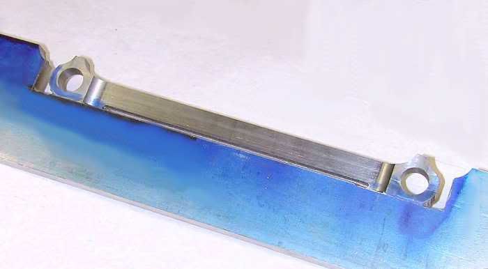
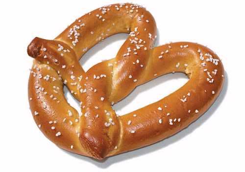
HOWEVER. . . when the last tendons of metal connecting the rods to the bar were finally cut I was surprised to find that they bore a much stronger resemblance to this photo than any connecting rods I had seen before:
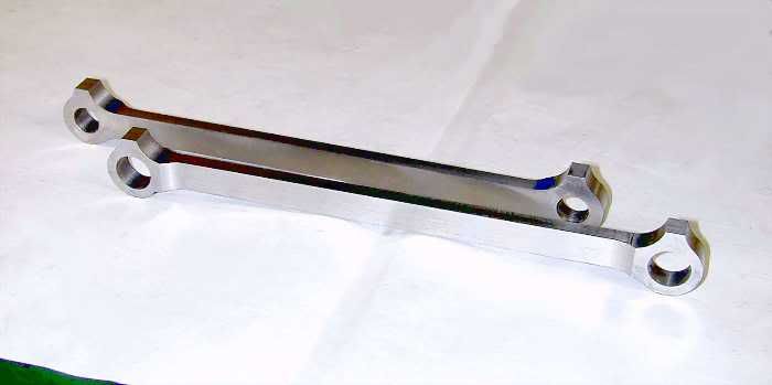
For size comparison, the rod journals are 8.500" center to center and are .500" wide at the thinsection and there was a bow at the center point of almost 1/4". I knew there would be SOME deformation but this was over the top. I think one of the reasons for this was that I took far more off the front of the rods than the back. I took equal amounts of material from the top and bottom of the rods and there was no deformation in that axis at all. In any case, some careful pressing with wood blocks in the vise and an occasional coaxing with a rubber mallet put them back into line, followed by radiusing the ends and boring. Hand finishing with files and emery will follow. So far so good.
HOWEVER. . . when the last tendons of metal connecting the rods to the bar were finally cut I was surprised to find that they bore a much stronger resemblance to this photo than any connecting rods I had seen before:
For size comparison, the rod journals are 8.500" center to center and are .500" wide at the thinsection and there was a bow at the center point of almost 1/4". I knew there would be SOME deformation but this was over the top. I think one of the reasons for this was that I took far more off the front of the rods than the back. I took equal amounts of material from the top and bottom of the rods and there was no deformation in that axis at all. In any case, some careful pressing with wood blocks in the vise and an occasional coaxing with a rubber mallet put them back into line, followed by radiusing the ends and boring. Hand finishing with files and emery will follow. So far so good.
")