Don1966
Senior Member
- Joined
- Jan 19, 2012
- Messages
- 487
- Reaction score
- 24
I just purchaseed a Myford Super 7 lathe and it came with 220volt motor. Well were I am putting the lathe this is to much trouble and if I wanted to move it I would have to do it all over again. So I decided to reconnect the motor and add more leads to it. This would involve taking the motor apart and tapping into the windings to add new leads. Anyway this is my documentation of that task to make it a dual voltage motor and connect it for 120 volts.
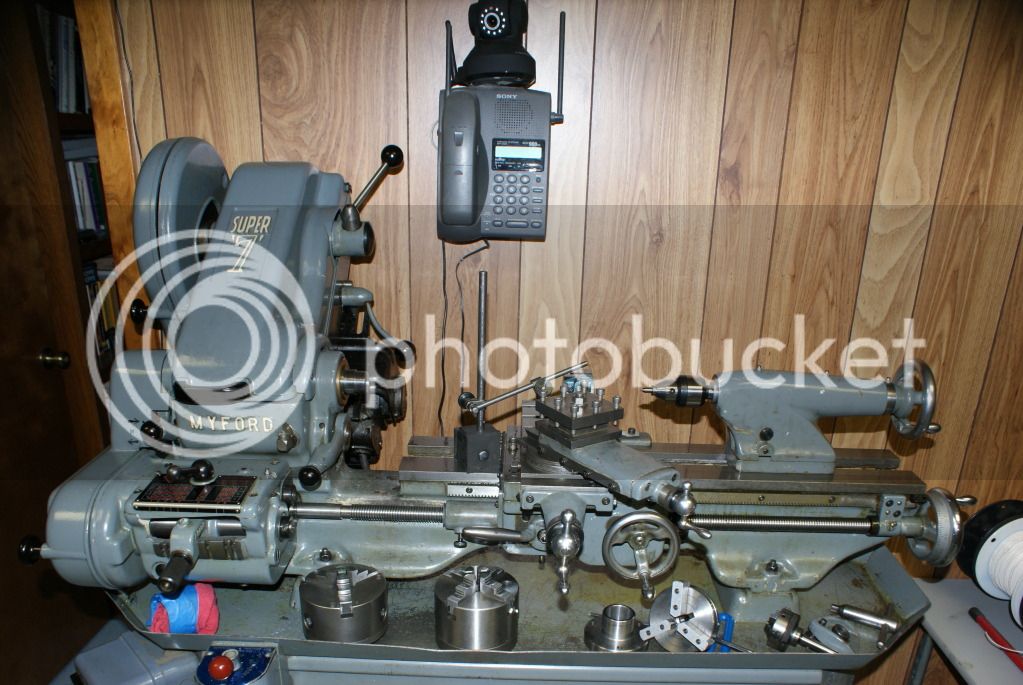
First the lathe
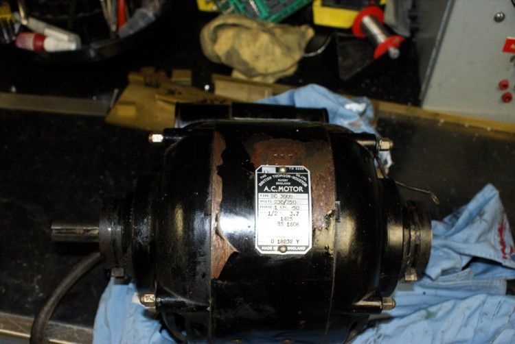
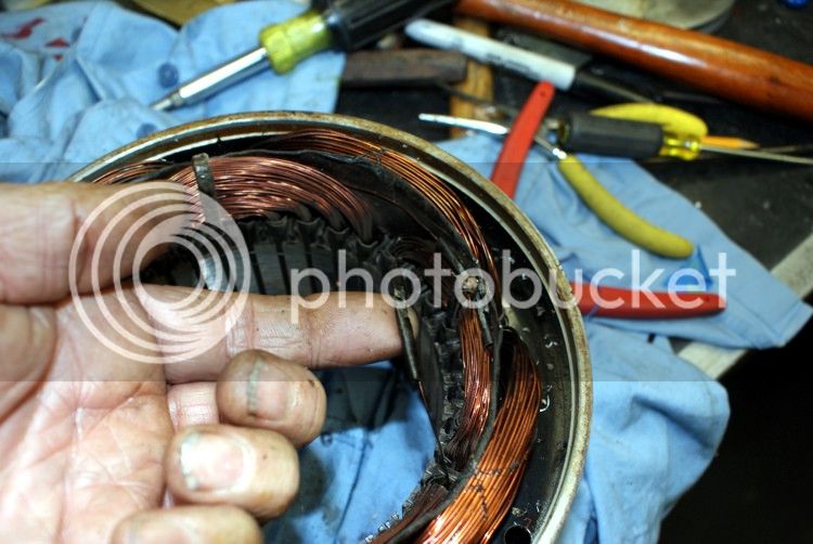
a look at the motor
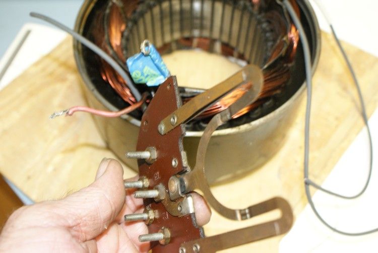
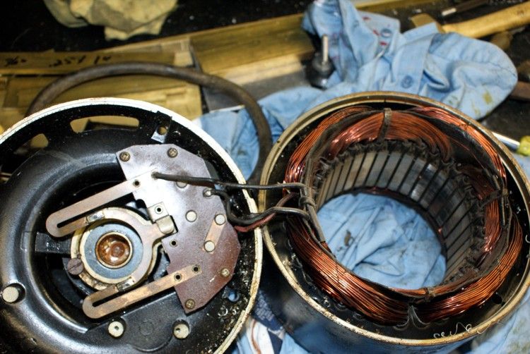
opening up the motor you can see the starting winding switch and the lead connection.
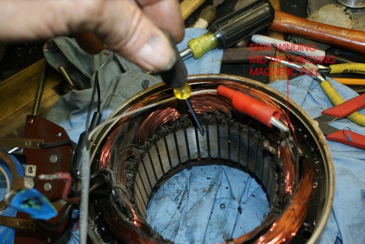
location of the starting winding center tap, which is the smaller winding closest to the rotor and there are four coils, making this motor 1800 rpm
at 60 Hz. You have to dig around and count two coil from the lead connect to the starting winding switch and you should see a jumper cross over to the next coil, this should be the center tap.
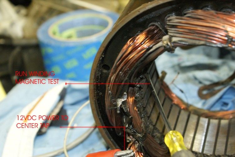
next I clean the connect up and connect a 12vdc power supply to the center tap and one of the main start winding leads and do a magnet test, just to see if two coils pulls my screwdriver toward them each individually. When I do the run winding I will do the same.
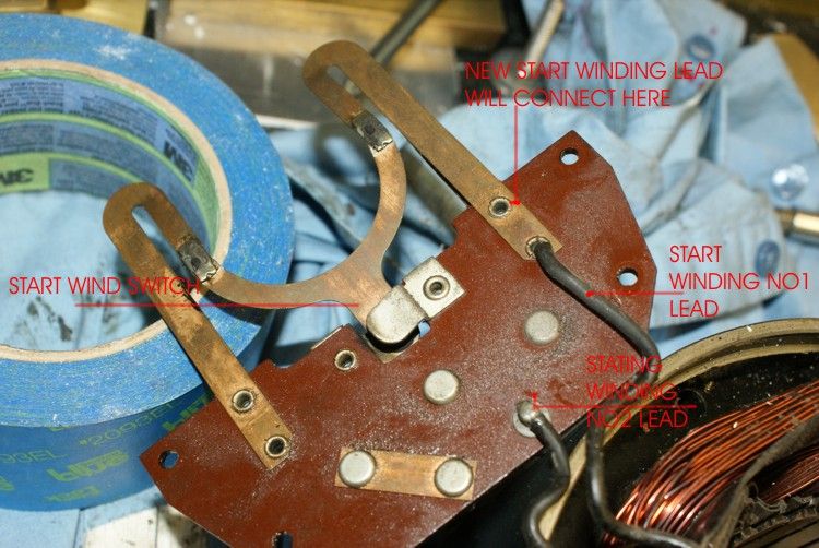
a look at the starting winding switch and you see my pointer showing where one of the new start winding leads will connect. I will label this wire No.5.
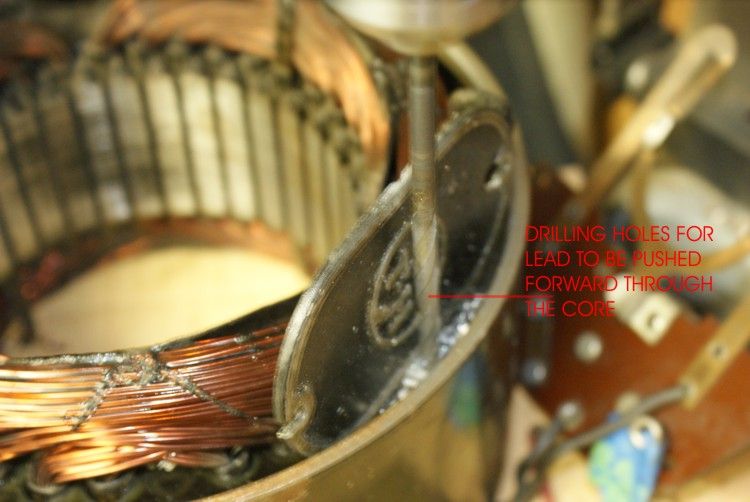
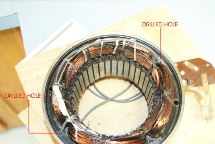
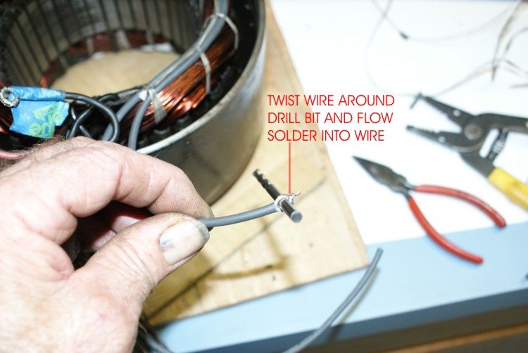
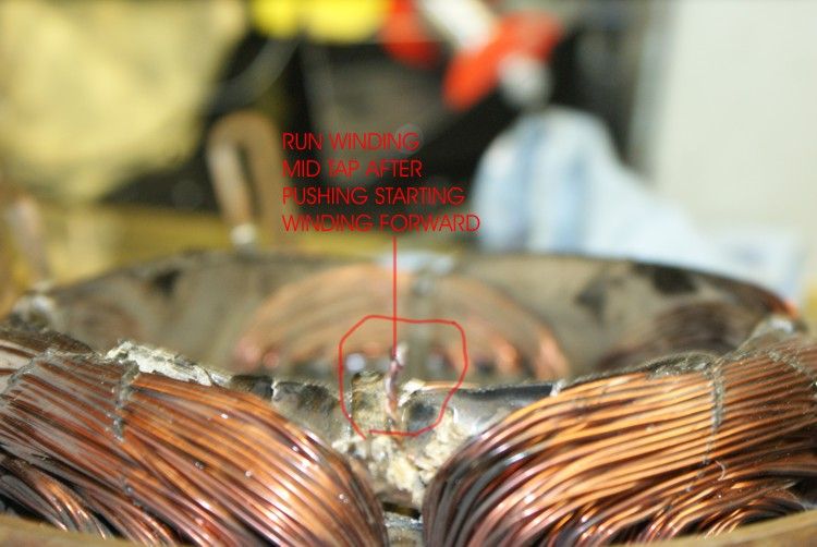
The running winding were a little harder to find the mid tap, but I located it on the opposite side of the stator and not the side the leads were located. This ceated more problems because now I had to drill two hole to the opposite side of the stator to get the leads to the proper side.
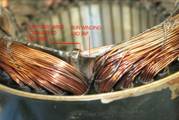
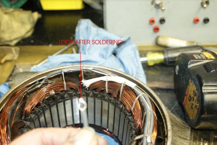
The centert tap run winding lead exposed.
Doing my center tap test with 12vdc and magnetic test, do this with both the exsisting run wind leads.
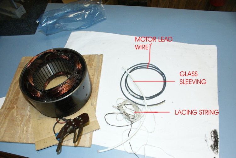
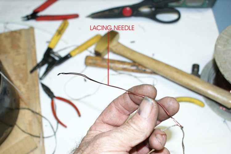
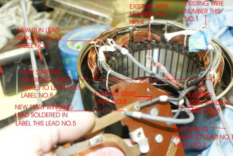
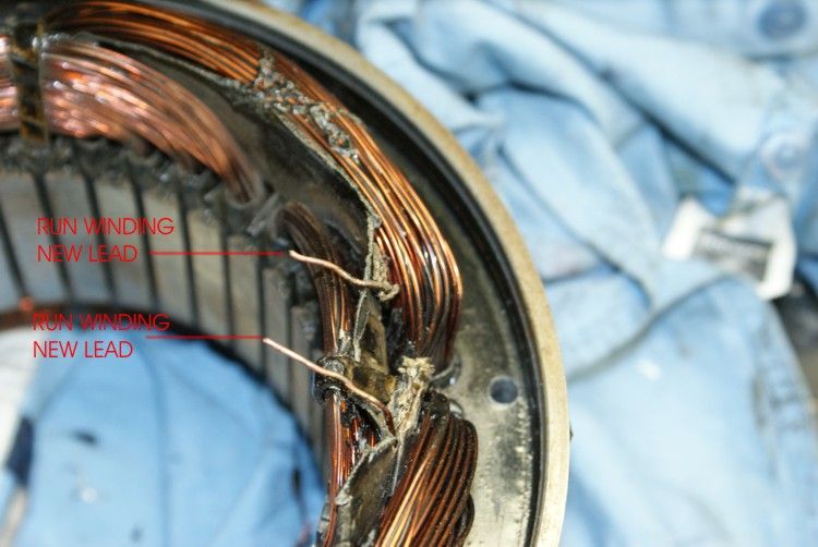
Breaking the connection ready for new leads. At this time I used my meter to check continutity from one of the cut leads to the existing leads, the first lead that reads I label No.1 and the other end No.2, I do the same with the reminding lead , but I label the last existing lead No.4 and the new lead No.3. These are standard US motor numbers for single phase motors. I will show a drawing of the connection at the end of the thread.
I will continue on a new reply.
\
Don
First the lathe
a look at the motor
opening up the motor you can see the starting winding switch and the lead connection.
location of the starting winding center tap, which is the smaller winding closest to the rotor and there are four coils, making this motor 1800 rpm
at 60 Hz. You have to dig around and count two coil from the lead connect to the starting winding switch and you should see a jumper cross over to the next coil, this should be the center tap.
next I clean the connect up and connect a 12vdc power supply to the center tap and one of the main start winding leads and do a magnet test, just to see if two coils pulls my screwdriver toward them each individually. When I do the run winding I will do the same.
a look at the starting winding switch and you see my pointer showing where one of the new start winding leads will connect. I will label this wire No.5.
The running winding were a little harder to find the mid tap, but I located it on the opposite side of the stator and not the side the leads were located. This ceated more problems because now I had to drill two hole to the opposite side of the stator to get the leads to the proper side.
The centert tap run winding lead exposed.
Doing my center tap test with 12vdc and magnetic test, do this with both the exsisting run wind leads.
Breaking the connection ready for new leads. At this time I used my meter to check continutity from one of the cut leads to the existing leads, the first lead that reads I label No.1 and the other end No.2, I do the same with the reminding lead , but I label the last existing lead No.4 and the new lead No.3. These are standard US motor numbers for single phase motors. I will show a drawing of the connection at the end of the thread.
I will continue on a new reply.
\
Don