zeusrekning
Well-Known Member
- Joined
- Dec 21, 2007
- Messages
- 448
- Reaction score
- 0
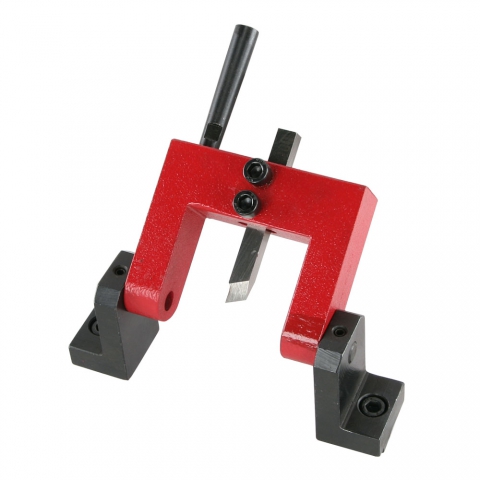
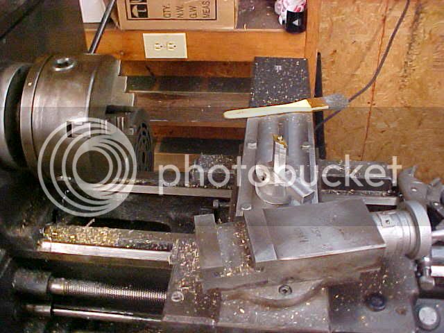
I finally made me a ball turner.
I didn't document anything while making the base but it is fairly straight forward. Round piece of aluminum turned knurled and bored for a tapered roller bearing I had laying around, then a slot milled for my tool holder.
I also made a steel plate to bolt to the top of the table with holes drilled and tapped for the ball turner to bolt to.
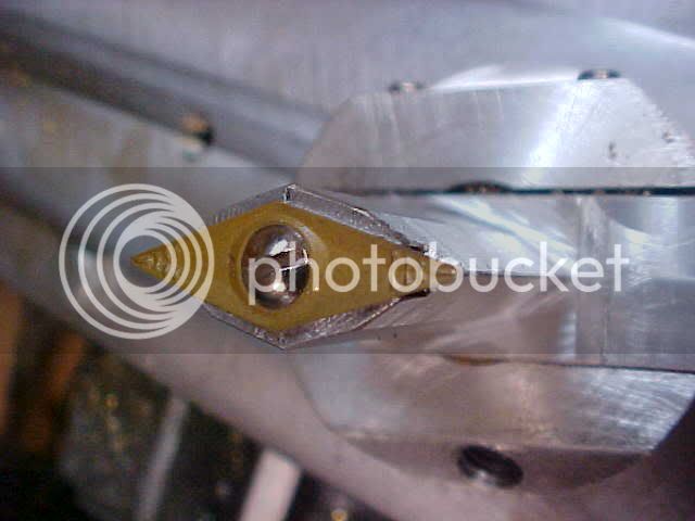
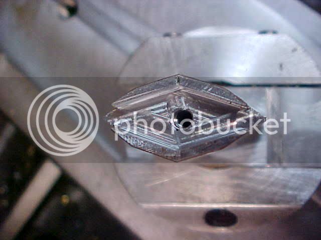
The part I did document was making the tool holder which was a first to me and the most complicated.
Unfortunately I'm short on time so I will run through it quickly with pics and add detail tomorrow.
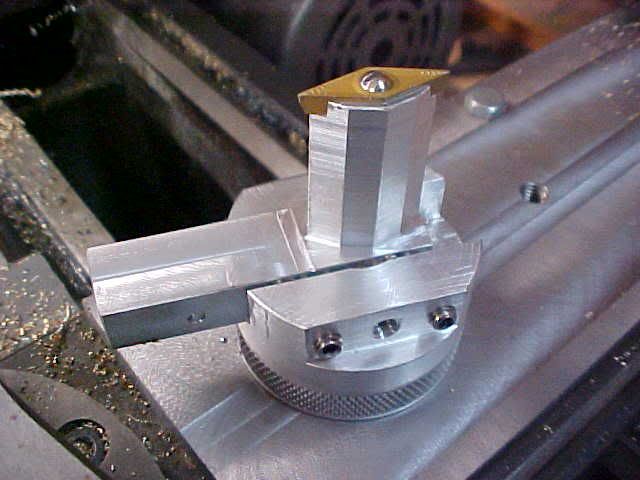
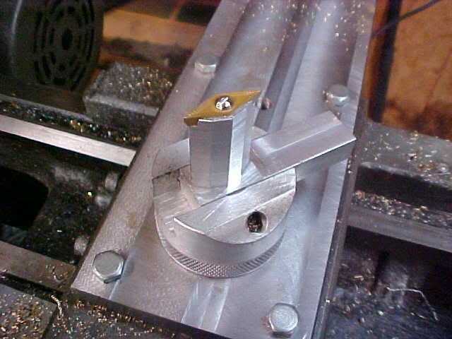
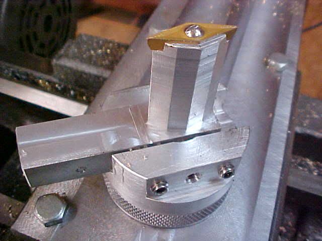
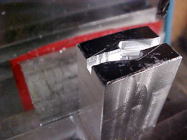
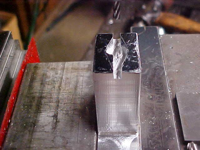
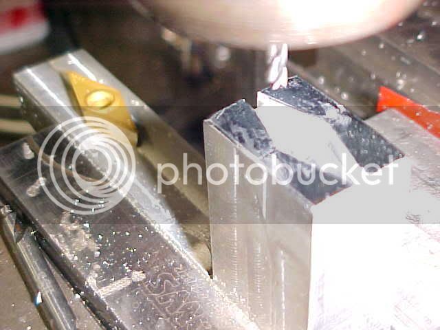
The main thing I did that worked out well was I used the rotary base that my Kurt vise in mounted on, It was a pain getting the tool centered but it made it easy to cut the tool profile.
The insert I chose to use was a 35deg VNMG style insert. I center drilled a hole where I wanted the center of the insert to be and then shimmed the tool holder blank out from the fixed jaw and located it in "X" so when the vise was rotated the hole I center drilled was aligned with the spindle. I then zeroed the DRO.
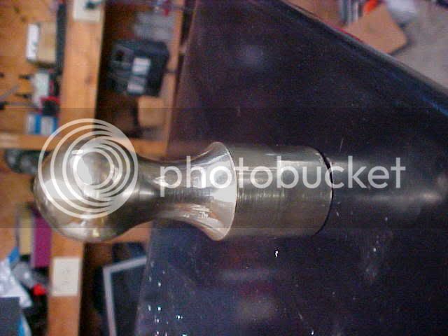
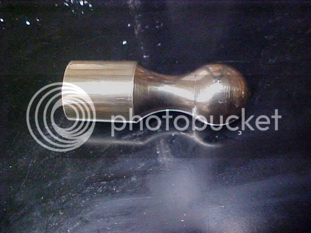
The greatest thing is when I brought my first part into the house my daughter (2 years old tomorrow) looked at it and said WOW! and now she want put it down. She is running around the house saying "My Pretty".")
I can't get all the images uploaded so here is what I have.
Tim
I didn't document anything while making the base but it is fairly straight forward. Round piece of aluminum turned knurled and bored for a tapered roller bearing I had laying around, then a slot milled for my tool holder.
I also made a steel plate to bolt to the top of the table with holes drilled and tapped for the ball turner to bolt to.
The part I did document was making the tool holder which was a first to me and the most complicated.
Unfortunately I'm short on time so I will run through it quickly with pics and add detail tomorrow.
The main thing I did that worked out well was I used the rotary base that my Kurt vise in mounted on, It was a pain getting the tool centered but it made it easy to cut the tool profile.
The insert I chose to use was a 35deg VNMG style insert. I center drilled a hole where I wanted the center of the insert to be and then shimmed the tool holder blank out from the fixed jaw and located it in "X" so when the vise was rotated the hole I center drilled was aligned with the spindle. I then zeroed the DRO.
The greatest thing is when I brought my first part into the house my daughter (2 years old tomorrow) looked at it and said WOW! and now she want put it down. She is running around the house saying "My Pretty".
I can't get all the images uploaded so here is what I have.
Tim