My 6th Engine

Home Model Engine Machinist Forum

Help Support Home Model Engine Machinist Forum:

This site may earn a commission from merchant affiliate links, including eBay, Amazon, and others.

BenPeake

Project of the Month Winner!!!
Project of the Month Winner
Joined
May 18, 2010
Messages
84
Reaction score
10
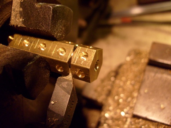
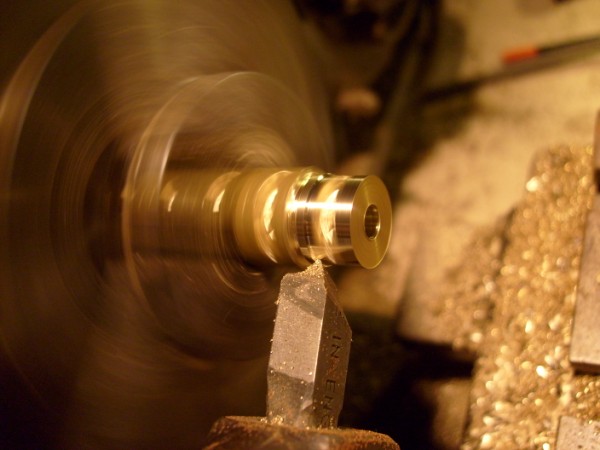
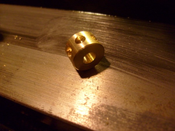
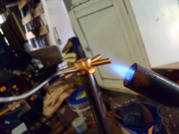
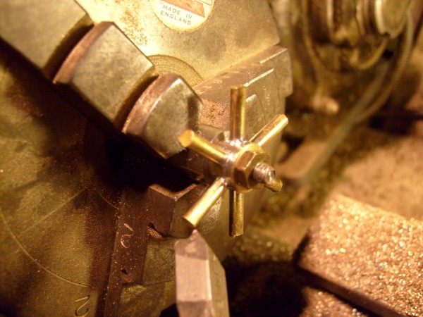
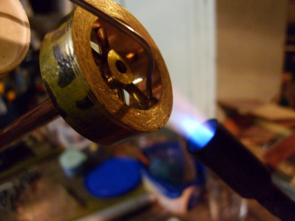
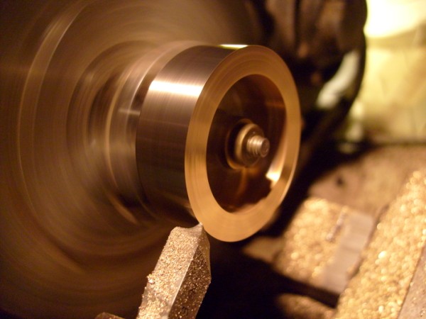
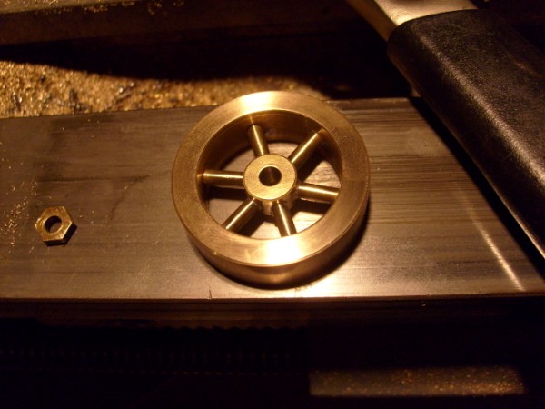
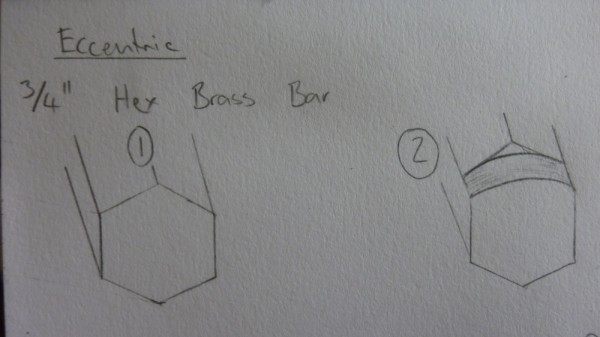
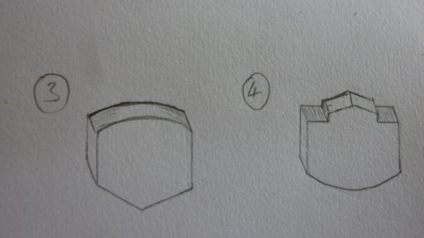
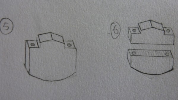
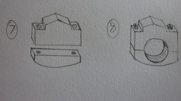
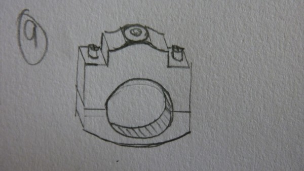
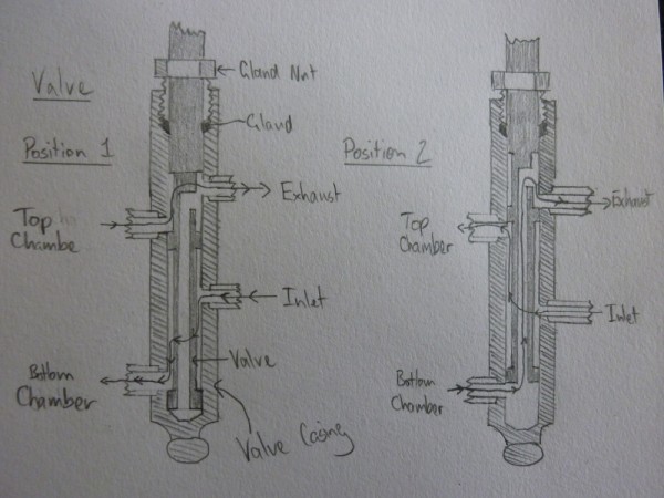
Here are a couple of pictures of the 6th engine I've built. It's a double acting 'upside-down' engine. My favorite part is the eccentric. There were no castings used in the making of the engine, not because I didn't want to use them, but because I haven't managed to get a foundry together yet - soon hopefully. It runs very well and I'm quite happy with it.

Steam%20Engine%20Bodkin%20No%202%20Front%20View.JPG


Steam%20Engine%20Bodkin%20No2%20Eccentric.JPG


Steam%20Engine%20Bodkin%20No%202%20Flywheel%20and%20Oiler.JPG


http://www.youtube.com/v/CmPlokiBrYE&hl=en_US&fs=1&

My other engines can be seen on my site www.peake-engines.com (among them is a super tiny oscillating engine which is for sale - it's less than an inch tall)

Thanks for looking,
Ben Peake
 
It's a beautiful engine, Ben. Nice eye for complimentary shapes and details.
Runs well!

Please feel free to introduce yourself and tell us your interests in the "Introductions" sections.

Also, you're welcome to show us your building sequences in the "Work in Projects" section.
We're very fond of projects and pictures here.

Dean
 
Welcome Ben, yes, by all ,means tell us about yourself and more info on such a delightful, eye catching engine. The crank is rather unique as is the entire arrangement. Did you do the design work or is this something that was 'modified' from something else? Way too cool 8)


BC1
Jim
 
Welcome to HMEM Ben.

Gorgeous build of the engine! :bow:

I really enjoyed browsing your web site.
It is very nicely done at that as well.

Rick
 
Did you say 6th? or 16th?! Man this thing looks great, congrats on a really classy looking little engine.
 
Thanks everyone for the kind words about my engine! To answer Jim's question, I designed the engine from my own ideas although, of course, we cannot help but be influenced by the many engines we've seen around the place.

I forgot to mention my other favorite part: that the knob on the top (you can see it best in the video) is actually a needle valve to adjust the flow of oil from the oiler to the crankshaft bearing.

Thanks again,
Ben
 
Ben,

Welcome to our forum. wEc1

Best Regards
Bob
 
Hey Ben,

I would like to ask you how you do your flywheels, eccentrics and valves. I am building a largeish double acting piston valve engine, and would like some pointers.
 
Hi Kaleb.

You're in luck with the flywheels - I have heaps of pictures of the method I used, however, you will just have to rely on my descriptions and I have done some quick drawings for you for the eccentric and the valve. So here are the flywheel pictures (obviously not the of the same flywheel as is on this engine, but they were both made the same way)

4631457341_876ee6d950_o.jpg


4632055066_885639f350_o.jpg


4631457491_d493e17fd3_o.jpg


In between these steps you have the opportunity to turn the spokes so they are more ornamental.

4631457537_8ac8b5780c_o.jpg


4632055268_2745507b57_o.jpg


4632055340_088e010350_o.jpg


4631457711_2816be1062_o.jpg


4631457781_ccb99de92b_o.jpg


The eccentric:

Step 1) Start with Hex Bar with a clean face.
Step 2) Mount it off-centre in a four-jaw chuck on your lathe, cut until it looks like the drawing

4631560105_3c911ae133_o.jpg


Step 3) Part off the work piece to the width you want it.
Step 4) Hand file the flats so the piece looks like the drawing

4631560163_c815cb5f09_o.jpg


Step 5) Accurately drill two holes in the center of the flats (they will be tapped so choose size accordingly)
Step 6) Cut into 2 pieces (keep in mind the final piece when deciding were to make this cut) with a hacksaw and tidy cuts in the lathe with a 4-jaw.

4632159428_99b4acdd01_o.jpg


Step 7) Tap the holes in the curved piece and drill the holes in the other piece so that the appropriate screws will slide through the later.
Step 8) Screw together and mount in a 4-jaw, drill undersized hole and bore to exact dimension.

4631560289_56f52c06af_o.jpg


Step 9) Mount in 4-jaw so pointed end is facing out, machine a flat and a curve up to the flat, center drill, drill, then tap with the thread which will be on the end of the conrod to your valve.

4632159552_728d80fb0d_o.jpg


Valve:

Here is are the drawings of the valve in both positions. Keep in mind all the parts have a circular cross-section and it should make sense. If not, ask away.

4632159612_50b3d7a137_o.jpg


Hope this helps, and good luck.
Ben
 
This sure is a pretty engine. Thanks for the drawings regarding the valve system.

Jack
 
Ben, I appreciate your method of constructing an eccentric strap from hex stock. Simple, elegant and relatively fool-proof (good thing for me :D) That is a very sweet looking engine.

BC1
Jim
 

Latest posts

Back
Top