Mousepower Dyno Testing

Home Model Engine Machinist Forum

Help Support Home Model Engine Machinist Forum:

This site may earn a commission from merchant affiliate links, including eBay, Amazon, and others.

Captain Jerry

Project of the Month Winner!!!
Project of the Month Winner
Joined
Dec 2, 2008
Messages
971
Reaction score
8
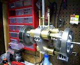
I got out one of my older engines to play with and this is how it started. This is on of my favorite engines for a number of reasons but mainly because it works so well. It is reliably self starting. It turns slowly at almost no PSI. It is well balanced and runs at high speed with little vibration. It is quirky locking. And it seems to produce good torque.

VIDEO


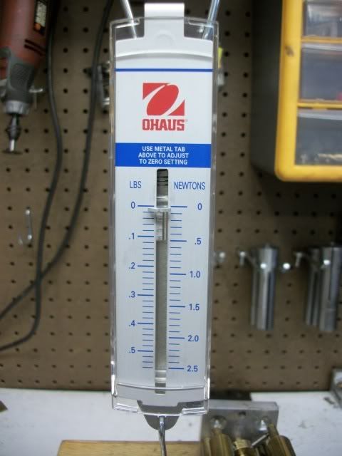
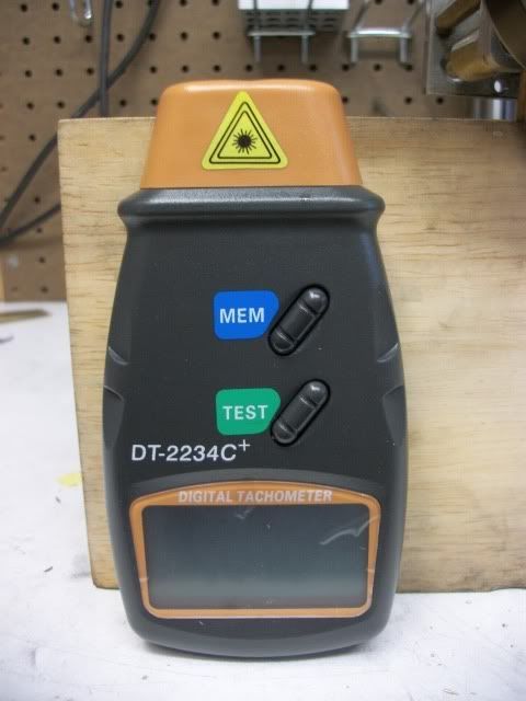
How good? I decided to find out. The tools needed are a non-contact tachometer ($16 from Amazon.com) and a sensitive scale. For about $300 you can get an accurate digital scale or for about $12 you can get an OK spring scale. I went with the spring scale ($12 from an E-bay store). The scale that I got has a capacity range of 0 - .5 Lbs marked in .02lb increments on a scale about 2 inches long. Perfect for the job.

mousepower022.jpg


mousepower025.jpg


mousepower023.jpg


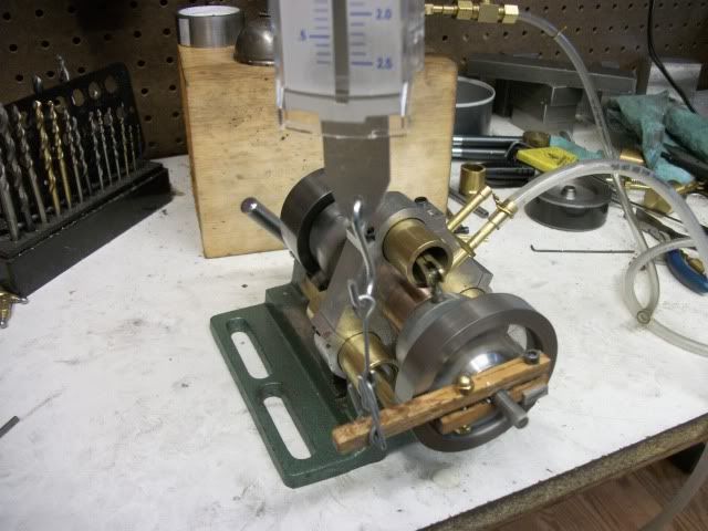
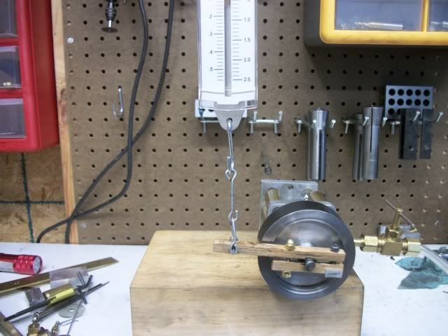
The Prony brake is a simple device made out of a short length 1/4" square red oak. One end is formed into a clamp that is adjusted with a SHC screw and fits around the bare 1/4" engine shaft that extends beyond the flywheel. At a point that is 2 inches from the center of the shaft is pierced by a pin to hold the hangar bracket of the scale. The torque applied by the brake will be directly read from the scale in (inch pounds)/2. The flywheel is 2.5" diameter so it was not practical to set the beam length to 1 inch. The scale is suspended from a shelf above the bench so that the beam of the prony brake is about level. The engine flywheel is wrapped with black tape and a reflective strip for the tachometer is applied.

mousepower020.jpg


Before using the brake, it was clamped down hard on a 1/4" shaft in the lathe and run for a few minutes to slightly glaze the wood clamping faces. When it was set up on the engine, the engine shaft was well oiled. With the glazed faces running on the oiled shaft, the load can be applied evenly without the stick/slip oscillation that I first got with the dry surface.

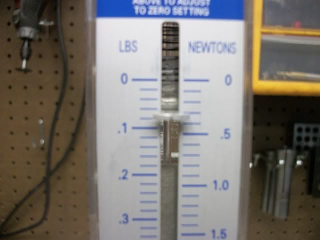
This is the procedure that I used. The engine was run up to maximum speed (about 2400 RPM @ 60 PSI). A little load was applied by turning the clamp screw. after 3 or 4 seconds to be sure that the speed and load were stable, the torque was read from the spring scale and and the RPS were read from the tach. This was repeated, adding to the load, reading the data, until I reached a point where the engine stalled. At about 400 RPM, the load began to oscillate to the point that readings could not be taken. I suspect that this is the point where the different cylinder efficiencies of the 4 cylinder engine were being encountered. More on that later if you are interested.

VIDEO:


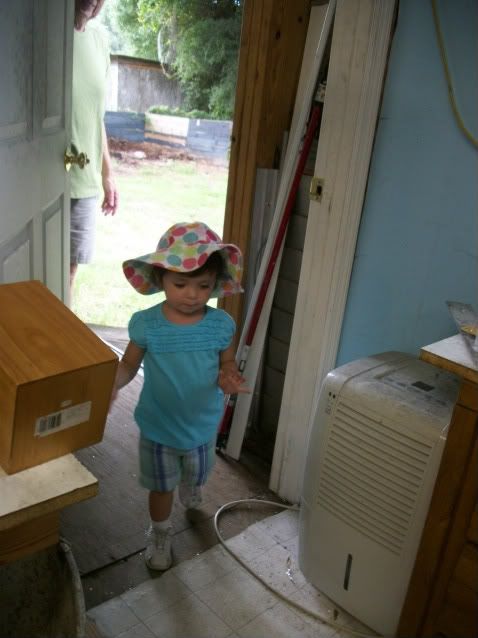
I was then interrupted by my supervisor (2yr old great grand daughter) , telling me it was time to feed the horses some carrots.

mousepower039.jpg


After completing that chore to her satisfaction, I took the data to a spreadsheet and produced two graphs. The first one shows inch pounds of torque vs RPM and the second shows Mousepower (Horsepower/1000) vs RPM.

WeebleTorqueDatasnip.jpg


WeebleTorqueSnip.jpg


WeebleMPsnip.jpg


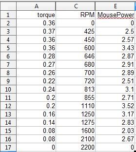
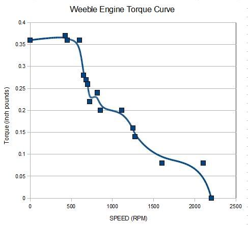
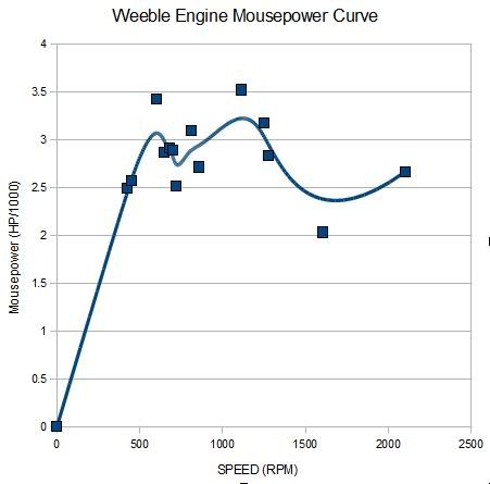
Only sixteen data points were used in this example and their is some obvious deviation from a smooth curve. The blue line is a B-spline smoothing of the data. More data points would produce a better result but this is good enough for non-contract work. The shape of the curve is about what I expected. Maximum torque ( .37 INCH POUNDS @ 425 RPM ) at low speed, maximum power (3.5 MP @1250 ) at higher speed.

Some points to note:

As the spring scale stretches, the load is overstated due to the effective shortening of the beam. I may work out a method to level the beam before each reading to eliminate this small error.

Even thought the compressor gauge shows 125 PSI, the gauge at the engine with the throttle wide open falls to 60PSI due to leaks and blowby in the engine. The pistons have no rings and the rotary shaft valve is unsealed.

Flywheel weight and design will have some effect. The engine will run well and reach above 2500 RPM with no flywheel but stalls easily if any load is applied. Tomorrow I will get more data points with this flywheel and also with one of the same diameter bu half the weight.

If you are reading this and there are no pictures or video it is because they are uploading. I will edit this posting when they are available.


Jerry
 
Jerry, I built a full on rolling road dyno for my other hobby - slotcars.

The orginal plan was to use an RC car motor add load it as the brake - that didn't work but injecting a braking current into it via some surge lamps did.

I calibrated the braking force by securing the car with a thin cord over a pully to a lead weight "anchor" - perched on a digital scale.

Loss of weight = thrust - which can then be translated into torque etc.

Similarly using a number of data points I found the relationship to amps and torque to be pretty linear.

All the other instrumentation followed from this.

The whole thing is built into a carrying case.

Keeps the guys at the local slotcar club "honest".

Attach a pully and cord to your pony brake and you eliminate the arm length variance problem.

Ken

Dscf0003.jpg
 
That is pretty cool Jerry, I want to do this with my TI4, but the digital tach gets interference from the ignition module and I would have to use my mechanical tach which also takes a tiny bit of torque away from the engine.

I got some nice finds on E-bay, a few Chatillon Push/Pull force gauges, at a fraction of their original cost and am needing more uses for them. This is perfect.

Since the lever is two inches, did you double the reading do get the in/lb data?

Kel
 
I love it Captn!

Use the digital fish scale as it is load cell based, not spring based.

No deflection so your prony brake arm doesn't move.


I like the slot car one too Ken! That was a bit of work!

Dave
 
Kel

How much shielding would it take to be able to use the tach on your engine? Some foil or screen? Right, the direct reading is doubled to get the value in inch pound.

Dave

My digital fish scale went into the storage shed when I sold the boat and I haven't seen it since, but it has an 80 lb capcity and I wouldn't trust the sensitivity at fractions of a pound and I don't think the digital display refreshes fast enough to reflect small oscillations. The spring scale is easy to read to a resolution of .01 pound. Adjusting the scale hanger to bring the beam level is not difficult.


Jerry
 
Jerry, I will have to try some experiments with sheilding the the optical timing light.

I hooked up this experiment to my TI4 this morning. I was able to get readings, but it is a real jumble trying to rev the engine, adjust the prony brake, hold the tach, and read all the dials at once. I am thinking about setting up a camera to view both dials at the same time, so I can go back and review the readings. Then I can concentrate on the engine and brake.

With the reading I think I got, .44 in/lb @ 6800RPM, I come up with .047 hp. This seems kinda week and I will have to refine my test a bit. I though It would at least be in the .2hp range.

Thanks for posting this Jerry, this is very fun. I love data.

Kel
 
I had so much fun playing with the Weeble that i decided to get another engine out and do some comparing. Here is a new video of an older engine. This is the opposed three cylinder axial engine that I built last year.

VIDEO


It is a good running engine, or so I thought. It is self starting at any position, it runs slowly and smoothly on very low pressure. Every moving part has a mirror image so it is perfectly balanced. It revs up smoothly when the throttle is opened and sounds powerful. It has almost three times the displacement of the Weeble. I can't wait to get it on the dynomometer!

Opposed3002.jpg


Preliminary results are not what I expected. :shrug: scratch.gif

More to follow.

Jerry


The results were very disappointing. This engine has a displacement of 1.45 cu. in. but only produces about 10 per cent more torque than the Weeble engine. The top speed is only 1250 RPM and so the maximum mousepower is actually less than the smaller engine.

I'm not sure why. The engine is free turning...it will coast for about 10 revs with a finger twist on the shaft. It may be that my small compressor is not enough for this engine. It runs constantly when the throttle is wide open.

The engine runs equally well in either direction, so I'm pretty confident in the valve timing. I have to manually swap the air inlet because I haven't designed the reversing valve BUT if I put my finger over the exhaust outlet, it makes no difference in the engine performance. Where does it go?

I've got some experimenting to do. New pistons are first on the list. Currently using aluminum in brass cylinders. A better fit with O rings is the plan. The current pistons have O rings but the grooves may be too deep as there is some leakage.

I'm also not sure that the air passages are big enough for this displacement but I don't know how to calculate the best size. The passages and the ports are 1/8" diameter. They can be made larger but with some difficulty so that will be the last change. Any help would be welcome.

Jerry
 
Hey Jerry, an exhaust-less engine - the green future needs such things - patent it.

"measure that which is measurable, make measurable those that are not" - Gallileo

Now you know it's just going to bother you until you get it sorted.

Sometimes ignorance is bliss.

I don't know that engine but it sounds like you might be exhausing one displacement into another (a timing issue ?) so the nett displacement is zero - well that wouldn't work at all but maybe it only runs by dint of some timing "errors".

I'm guessing here - but you did say - any suggestions.

Regards,
Ken
 
Got it all worked out. New pistons and new rods. The old pistons were such a poor fit that most of the pressure was just blowing past. These are single acting pistons so there is no packing gland. The new pistons are of a very different design. The piston is rigidly fixed to the rod and has a spherical surface that allows for misalignment of the rod (less than 2 degrees) and is sealed with an o-ring. There is an increase is sliding friction so the engine will only coast for a few revs.

The previous piston seal was so bad that it could not generate any exhaust pressure through the valve. I guess all of the exhaust just blew out the end of the cylinder. Blocking the exhaust had no effect on the engine because there was no back pressure.

With the new pistons installed, the improvement is dramatic. Maximum speed is now about 2100 RPM, Maximum torque is literally 'off the scale', power output is over 25 MousePower; almost a 10 fold increase, and there is enough air pressure in the exhaust line to run the little Weeble engine (slowly). Torque is off the scale because my little spring scale has a max reading of .56 lbs and with a two inch beam on the Prony brake that translates to 1.12 inch pounds at a bit more than 1/2 throttle.

At the next opportunity, I'm going to remake the Prony brake with a 4" beam which will give me a max scale capacity of 2.4 inch pounds. This little experiment shows the value of the dyno testing. I was happy with the engine before. It was a "Runner" so I put it on the shelf and moved on to something else. Now it is a much improved runner and is back on the bench for refinement. Reversing valve is first on the list.

Jerry
 
Thats Awesome Jerry!

I am very glad you made this thread. This is a relativly easy test to perform, and the results are indisputable.

Kel
 
Something got me thinking.

Can we check our torque wrenches with this device?

Kel
 
Kel

I guess you could check your torque wrench with it. All you have to do is hold the tachometer in one hand and spin the wrench about 500 rpm with the other. If you try it, be sure to get video.

Jerry
 
:big: :big:

OK, Without the tach, and the prony brake tightened all the way, then maybee?

Kel
 
I've measured running torque by just that technique...string wrapped around the shaft and pulling with a spring scale.


Dave
 
kcmillin said:
:big: :big:

OK, Without the tach, and the prony brake tightened all the way, then maybee?

Kel

Your way has some technical merit but it looses something in entertainment value.

I did some more refinement today, mostly valve timing. There is only one valve but you have to time both spider plates. Its mostly by sound and feel but the top speed in either direction should be about equal. When the two spider plates are in sync, (180 degrees out of phase) all vibration ceases and it runs like silk. Just a fraction of a degree off and the vibrations are felt.

I increased the beam on the Prony brake to 4 inches sot the max torque reading is .56 lbs x 4 inches = 2.36 in. lbs. The engine now produces that at about 900 rpm. It will produce more torque if is loaded up and the speed drops to around 500 rpm but the scale is bottomed out so I don't know how much. I guess I should have a six inch beam.

Not only does it show good low end torque but as the following video shows, It will self start reliably under a torque load of 1.8 inch pounds. In this video, the exhaust outlet is connected to the Weeble engine which also self starts and runs at about 500 RPM under no load.

VIDEO


If you build a Prony brake like this and run the engine under heavy load for 5 minutes, do NOT! grab the shaft between thumb and finger. You may not hear the sizzle over the compressor noise.

Jerry
 
If you are tired of seeing this engine, just tell me. I seem to post an update as I think of something new to do with it.

It now has a reversing control valve and a mount. Not so much a display mount as a working mount. It is highly unlikely
that my engines will find a point of display anywhere in the house. If a visitor really wants to see it, we'll go to the shop.
If we go to the shop, we'll have to be able to run it so it gets a working mount.

The mount has several functions. The engine is mounted close to the right end so that the overhang will allow larger flywheels
to be mounted. There is space on the left of the platform for other uses. Next in line will probably be a planetary gear
box that will provide a 5:1 reduction or increase. A generator of some kind with variable load bank. And a flywheel governor.

I don't think there will be any 'bling'. Im afraid that if I got it all shiny or painted, it would never get to run again.
I can waste a lot of time just tinkering with it.

The stand also is fitted a a storage/travel box. These things are lots of fun to take through airport security if you have
plenty of time.

The video shows the engine with the control valve running forward and reverse. The strange noise that you hear at the
beginning and about halfway through is a hard rain on my shop's tin roof.


[ame]http://www.youtube.com/watch?v=YR7SH5YDQGY[/ame]

Thanks for watching,

Jerry
 

Can't get tired of watching that! I love the wobble plate action.

It's a beautiful engine Jerry.

There is a wobble plate vacuum engine in MEB magazine which you have inspired me to want to build.

 
Thanks Kevin. I'm glad you like it. Wobble plates are fun. This is actually a Z-shaft design. It should be a simple engine to build, at least the next one should be easy. This one was a bear since I was learning machining (still learning) and 3-D modeling (still learning), and design (still learning) at the same time. I have no training in either so I'm free to do it in an unorthodox manner.

Due to lack of training, I have been reluctant to post plans for the engine but I have noticed some other members have posted plans that are more like narrative build notes with key dimensions that have been well received by the forum.

Jerry [977]
 

Latest posts

Back
Top