IH Mill CNC Conversion

Home Model Engine Machinist Forum

Help Support Home Model Engine Machinist Forum:

This site may earn a commission from merchant affiliate links, including eBay, Amazon, and others.

BobWarfield

Well-Known Member
Joined
Dec 27, 2007
Messages
1,151
Reaction score
1
After making a series of modifications to increase the rigidity of my IH mill and add a one shot oiling system, I'm now turning to the conversion of the mill to CNC. I'll be working with an Industrial Hobbies "mechanicals only" kit and using my own servo motors and electronics.

Let's start with the design and layout of the electronics. I purchased a NEMA-style enclosure from eBay which I mean to mount to the side of a rolling tool cabinet I got from Sears on sale for Labor Day:

GladiatorClosed.jpg


and here is the NEMA enclosure:

P1010905.JPG


Some kind of phone system had been inside, I think. I'll be clearing out all the guts. To get the door open I had to make a little key as well:

P1010902.JPG


Some lathe work, cross drill on the mill, and a 1/8" roll pin and I was in like Flynn.

<continued>
 
I'll be using the ubiquitous Geckodrives to control my servos. I've used them in the past and like them well. This will be my first time for servos instead of steppers though. Servos have a number of advantages over steppers, though they are slightly more expensive--perhaps 20-30% all told. Their chief advantages are in speed and accuracy. They maintain torque for a broader rpm range, and they are closed loop, meaning they have a sensor that measures how far they moved. A well-designed control system can compensate if the motion comes up short, and this is what the Geckodrive does for you.

I'm going to create what I call "axis modules" for each axis of the mill. I'll start with 3, but Mach 3 (the software on the PC that controls the servo motors) can manage up to 6 axes. I may actually use all 6 over time, so I want to make provision for expandibility in my design. Here is a CAD drawing of what a typical axis module would look like:

AxisModule3D.jpg


Here's what you get. The red box on top is a Geckdrive. It is mounted to an upside down heatsink. Remember, this is a very smart little motor controller, but it can manage up to 20 amps at 80V. That's about 2 HP, and it is a little tiny box, so I like to use a heatsink!

Underneath is the front panel. The 3 components directly under the heatsink are a socket for the servo motor power cord (I plan to use standard IES computer-style three prong cords), a connector for the encoder on the servo (that's the sensor that tells how far it has moved), and a 3AG fuse holder. That round purple cylinder is the back of a 15 amp ammeter. The ammeter will tell me the load on the servo. It's handy to know how hard the machine is working when you're doing things like tuning up the gibs. One of the commercial VMC (Vertical Machining Center) recommends tightening the gibs on their mills to 30% of the maximum load for the axis. Tighter gibs run more accurately right up until you get them too tight. On a CNC, there is no feel, so a meter is helpful. Seeing loads creep up would be an indication to try the one shot oiler first, and then re-adjust the gibs if there was still to much trouble moving the axis.

OK, now these axis modules will be mounted in my NEMA enclosure so there is room for up to 6 of them. That looks like this:

EnclosureLayoutSchematic.jpg


4 modules accessed from the front, and 2 more in the rear. Also inside the enclosure will be the DC power supply for the servos, a board to interface the PC to all of this, and some relays to help control the VFD for the spindle and optionally coolant or compressed air to blow the chips away while cutting.

I'm not going to try to squeeze a PC in here, though a little larger box and that would certainly be possible.
 
While I'm planning and constructing the electronics, there are a myriad of other little things to do on the mill. One of them is to install the home/limit switches. These are precision switches that serve a couple of purposes. First, they stop the mill from running an axis off the edge and hurting itself, and potentially the operator too! :eek:

Second, they are precision so that the machine knows to a very close degree exactly where the axis is when the switch is tripped. When a CNC is first turned on, it will test those switches to calibrate its position.

Here is the X-axis limit switch mounted just where'd you'd mount the switch for a power feed:

P1010895.JPG


The two pins are triggered by stops mounted on the table's side T-slot.

Here's what's inside one of these limits:

P1010897.JPG


These are optical limit switches. What happens is a little shutter crosses a light beam to trigger the switch. There are a number of other kinds of limit switch available. One of the chief things to look for is a switch that can survive coolant and chips. This one is inside a sealed enclosure with a rubber gasket.

P1010896.JPG


The other 2 axes work by those long metal rods. A color on the rod allows you to set where the switch is tripped. The rod runs through a hole in the moving block which is on the part of the axis that moves. The block will run up against the collar on the rod and trip the switch.
 
Getting back to building the axis modules, I started with a big piece of surplus heat sink material from eBay. It was too big for my bandsaw or chopsaw, so I sliced it up on the mill:

P1010887.JPG


P1010889.JPG


Next step was to mill off the fins to create a mounting rail on 2 sides:

P1010892.JPG


Making 6 axis modules involves a lot of repetitive tasks, so you'll see me using stops a lot so I just setup once and can do each part quickly.

Then I used my CAD program to make a 1:1 actual size template for drilling. I glued that to one a piece of steel plate to make a drilling jig (yes, this jig will guide the bit as well as locating as a fixture does):

P1010900.JPG


Kant-Twist clamps made it fast to drill my holes in each of the 6 heat sinks.
 
I had some 304 (yucky stuff) stainless rods laying around that I threw on the lathe to make 4 legs for each module. 304 is hard to cut, so I simply drilled the proper sized holes for tapping in the ends and faced the ends. I finished by parting to make sure the legs were all the same length.

I managed to break off one of my cheap 4-40 taps in a heat sink (hate the taps that come with the sets, but I got in a hurry, DOH!), so I had to stop until new taps arrived from Enco. A brand new spiral flute tap makes even the 304 stainless not that big a challenge!

Here is a heatsink on its legs with a Gecko mounted:

P1010909.JPG


Next stop is to make the sheet metal panels for each axis module. I'm only going to do 4 panels for the front. The 2 rears will just be blanks until (and unless) I actually need the modules.
 
Hey Bob!

That's looking great. Got a couple of questions for you as I start my CNC conversion this week.

How is the epoxy granite mix working for you? Do you think it is going to be worth it?

What are you going to use for a controller? I am getting a CNCbrain from SR robotics:


Click the pic for a link.


Eric
 
RE the Epoxy Granite, it is too soon to tell. It was very easy to do, and the castings sound noticeably more dead when you rap them with a wrench. But, I have no real cutting experience on which to base an informed opinion. I am optimistic about it, however.

RE controller, I plan to go with a SmoothStepper. One piece of advice--don't go too far out on the bleeding edge. I did that on my last CNC project with a GRex and never got it finished. The controller wound up being orphaned and the Mach 3 support for it was never quite right. Ever since I resolved not to do anything but the #1 or #2 most popular controller for Mach 3. Right now that would be the parallel port or Smoothstepper.

Cheers,

BW
 
Bob, many thanks for posting this. CNC is going to exist in my shop one day. It is a "down the road" plan, but every little bit of information that I can tuck away will be a great benefit when the time comes. Until then, I am enjoying the shared journey with yours and can't wait to see it come to life!
 
A bit more progress to report after having most of yesterday afternoon available in the shop.

First, I soldered the cables on my servo motors. They come with short tails, so I just soldered on some IES power cords to extend their reach to 10 feet. These are the same power cords you'd use on a computer with the distinctive three pronged connector. For splicing, I like to protect each conductor with a piece of heat shrink tubing and then protect the overall splice with another piece. Unfortunately, I didn't have the latter 1/2" tubing on hand, so I did 2 of the cables with electrical tape wrap. When I ran out of even the smaller diameter I had to make a run to Radio Shack for it. Here are the three servo motors that replace my 3 handwheels on the mill:

P1010920.JPG


You can see an additional white connector on each motor that looks like a serial port connector for a computer. That's the encoder connector. Encoders are one of the big things that separate servos from steppers. You can drive a CNC with either, but servos offer higher performance (at a higher cost, natch!) than steppers. I like using standard connectors so I can buy off the shelf cables already made up. Hence the IES power cords, and now these serial port connectors. The latter were installed by Homeshopcnc, which is where I got my servo motors. To give you an idea, these are 850 oz/in torque motors that cost $235 apiece with the encoder housings, so they're not cheap for this kind of performance. Steppers in that range would cost circa $130.

Next, I managed to finish a couple front panels for my axis modules. Here is one mocked up with the parts, but not wired:

P1010922.JPG


So the encoder plugs in to the left of the fuse, and the servo power cord to the right. I can get at the fuse without opening up my enclosure with the panel mounted holder. The ammeter is a peculiarity of my setup. I wanted to measure the current draw of each axis as a way of understanding how "tight" the axis is in order to adjust the gibs and monitor wear. Remember, you lose feel for gibs with a CNC!

Here is the back of the panel:

P1010924.JPG


As you can see from the photos I have an issue with meter clearance and the mounting bolts, so I made an oversized hole to try to create some "wiggle room". This happened due to an error in laying out the big square face during the CAD design. What I need to do is relocate the whole meter 1/4" down the panel and all would be well.

I've gotten it close enough, I think. I can't go much further or I'll lose the mounting holes for the meter as you can see in this behind shot. In the end, I'm planning to remake these panels anyway once the CNC is up and running. I'll make them out of 1/4" aluminum plate and put some engraving and other decorative touches on so they'll look a lot nicer.

Still an awful lot to do on this project!
 
More updates.

Been cutting openings in the enclosure with an air shear (nice tool!):

P1010925.JPG


Love my air tools!

P1010927.JPG


And I'm mounting all sorts of little CNC4PC boards plus an Antek DC power supply:

P1010944.jpg


Getting closer to being able to spin a servo or two...
 
OK fans, there is finally more progress to report. I've spent the last 2 weeks trying to get my electronics wired up and working. I finished the initial wiring 3 days ago, and since then have been feverishly trying to debug it all. I am happy to say that I can now spin one servo under Mach3 computer control. Yay!

But what an ordeal it was getting there!

If you want the full story of how I debugged this silly thing, I captured it on a page so you can see how I went about it:

http://www.cnccookbook.com/CCMillCNCDebugging.htm

It's a painful process as not all of the relevant information you will need is captured in one single place. Some of it was out there, but a lot of it I just had to figure out on my own.

Here is a concise list of all the things I had to change from my original attempt to run:


1. Set CNC4PC Master Control Board DIP switches for G320. It acts funny on the other board types whether or not Err/Res is connected.

2. Discovered I had mislabeled the leads from my front panel for the "Start" and "E-stop", so they were connected backwards.

3. Reverse the motor connections because they were backwards compared to what the encoder indicated, causing an immediate servo fault.

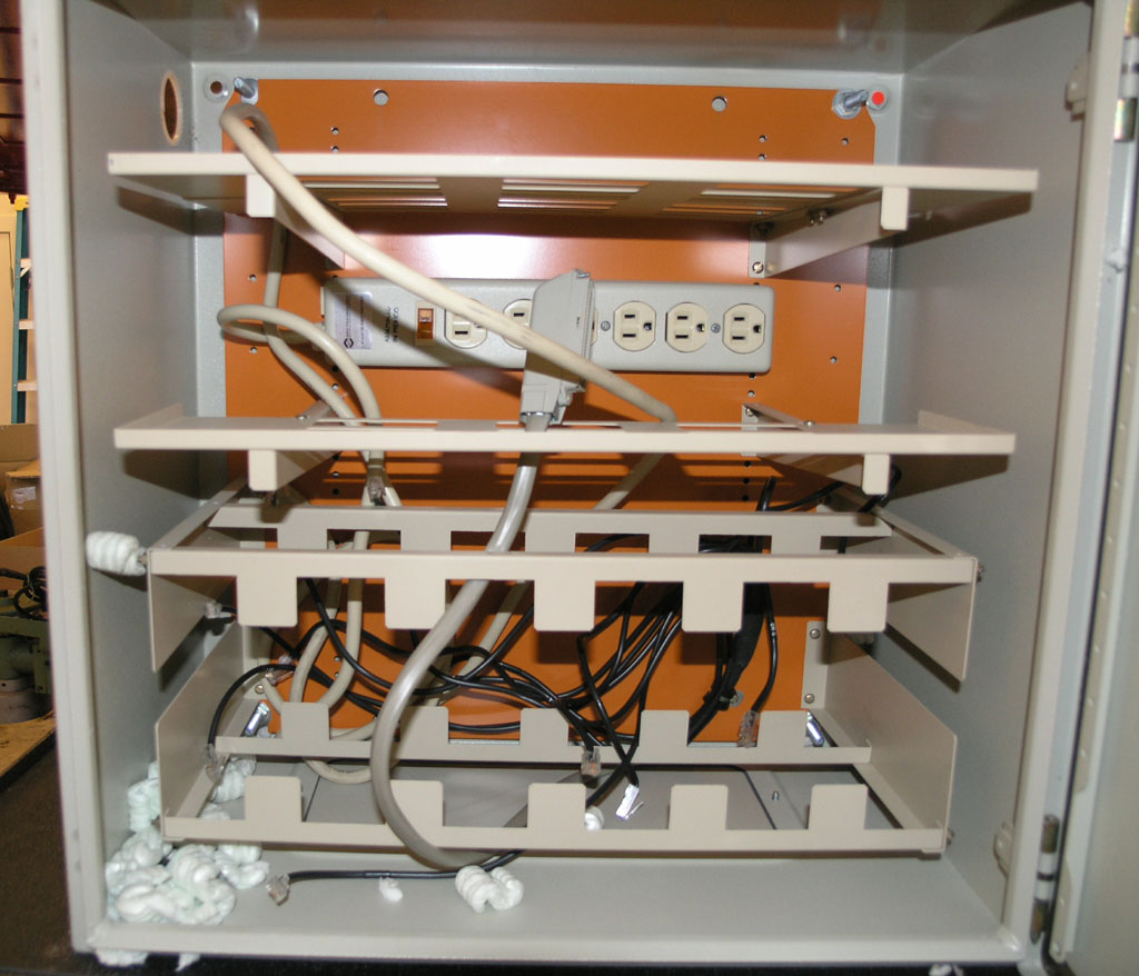
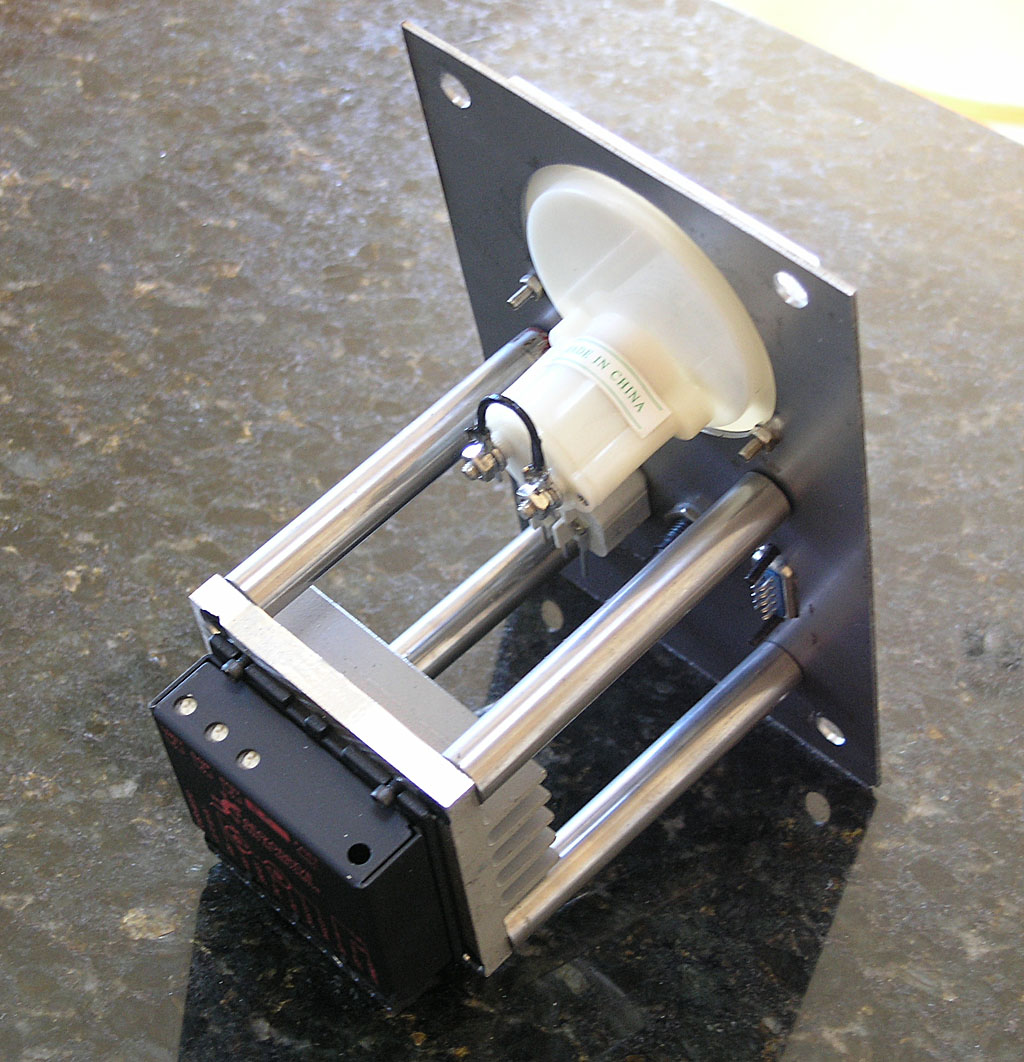
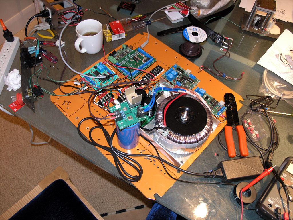
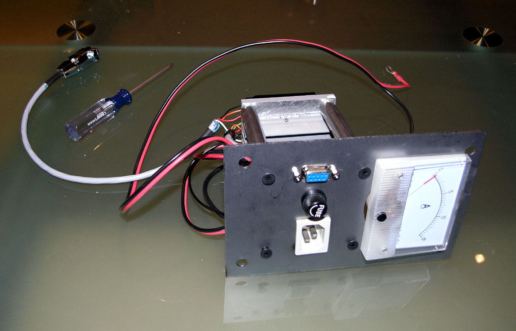
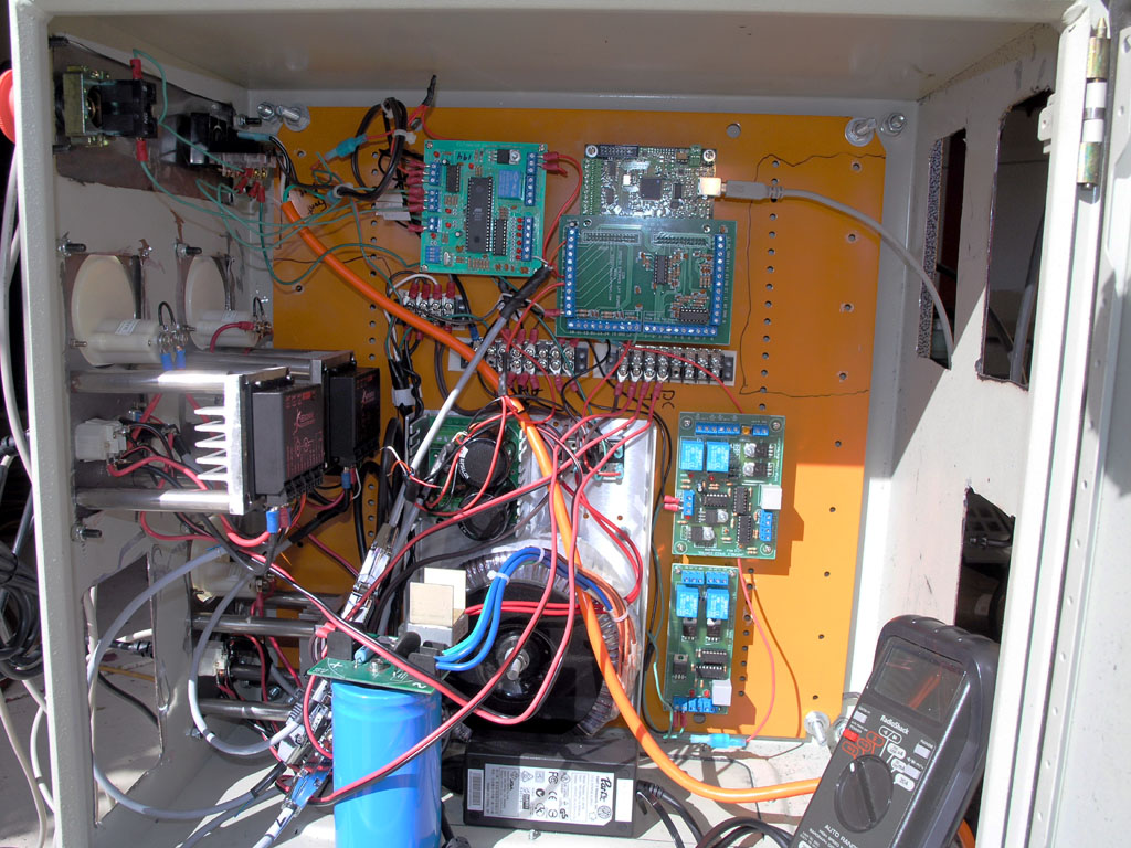
4. In doing #3, I reversed the wrong leads and had to replace the power supply PC board. You can see my substitute sitting there atop an electrolytic capacitor. I don't think I blew the Gecko, amazingly! My only excuse for that bone-headed mistake is that it was late at night and I have the flu. This needed the electronics equivalent of measure twice cut once!

5. Connect a 47K ohm resistor across pins 1 and 3 of the G320 to ensure the bridge initializes properly. This was buried in a hard to find Mariss note on CNCZone. He says there that this fixes power on fault problems and will be built into the next generation Gecko servo controllers.

6. Now I was getting the servo to hold position, so I played with the tuning trimpots a bit.

7. In Mach3, set Step/Dir to ActiveLo. Set pulse width to 5 (the pulse width may be ignored for Smoothstepper, but I was taking no chances).

8. Connect "Common" on G320 to +5V on breakout card instead of Ground. Another one that's easy to miss unless you read a lot of posts on various boards! I had it connected to Ground for a long time because that's what the word "Common" meant to me. I finally found an old picture of a G320 where the connection said +5V and that gave me the idea.

9. Set up the proper motor tuning parameters on Mach3. IH says 115 IPM speed and 0.15g of acceleration, according to another post I found. I also needed 28,240 steps to move 1".

10. Set the Smoothstepper jumpers to actually provide +5V to the breakout board. Otherwise, the terminals marked "+5V" are 0V! I discovered this as I was clutching at straws and decided to see if I had missed some jumper or DIP switch on the Smoothstepper.


Now I can spin the servo this way and that with Mach3. It can still fault if I rapidly change directions at full jog, but that's just tuning and I need to set it properly on the actual machine instead of with servos flopping around on the floor.

I must admit that per the discussion on the other thread, it was a lot harder to spin a servo than a stepper. In general, I encountered a lot of less than obvious things including the CNC4PC DIP switch settings, need for the 47K ohm resistor on the Gecko, and bizarre experiences with "Common", which has to be +5V, and which didn't get +5V until the Smoothstepper jumpers were enabled. I may still have a problem or two to diagnose. This thing is breadboarded at best, and the Err/Reset still needs test and hookup.


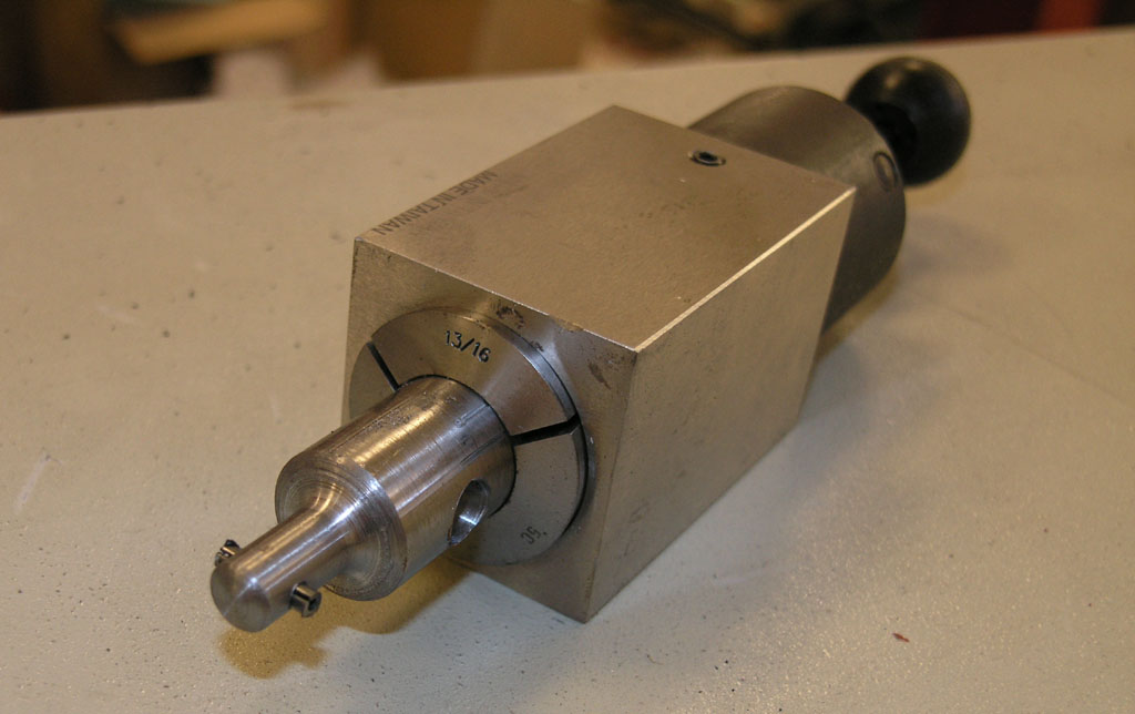
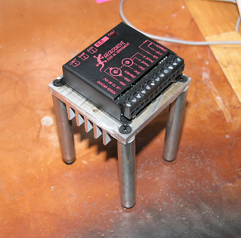
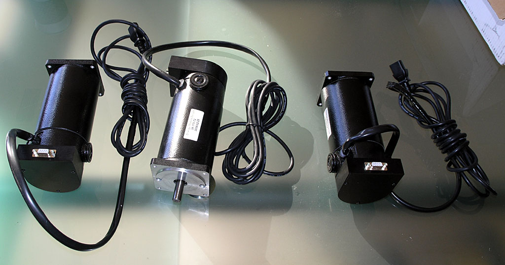
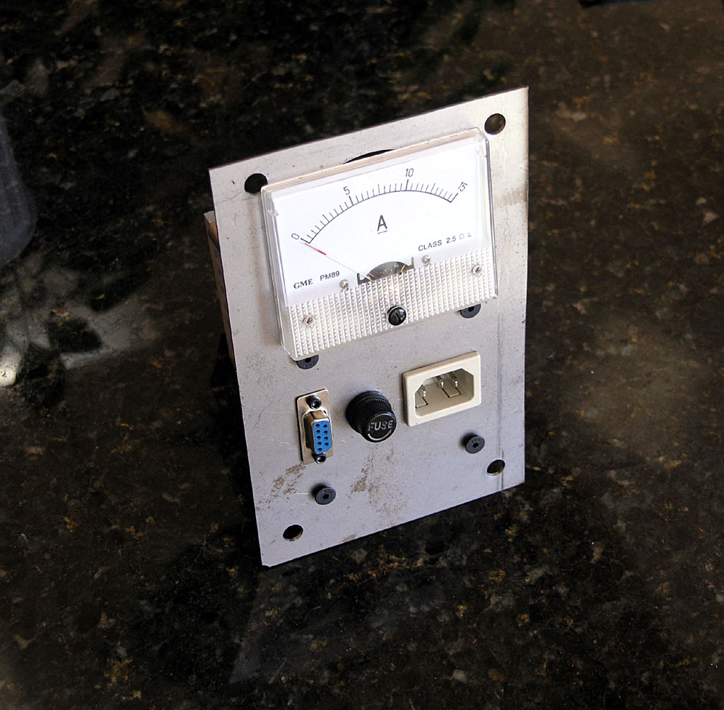
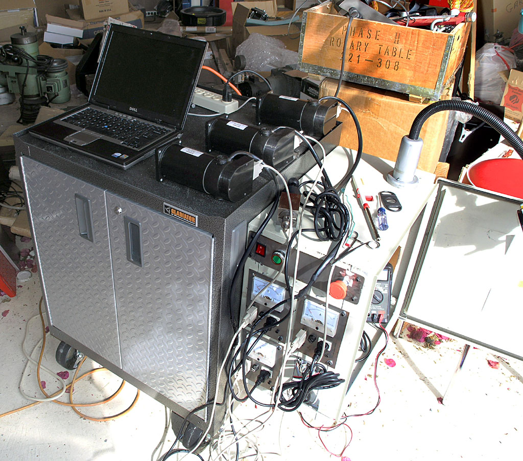
Here are some photos of my CNC electronics testing lab on the dining room table (my wife is glad it seems to be working and I'm cursing a lot less!):

P1010986.JPG


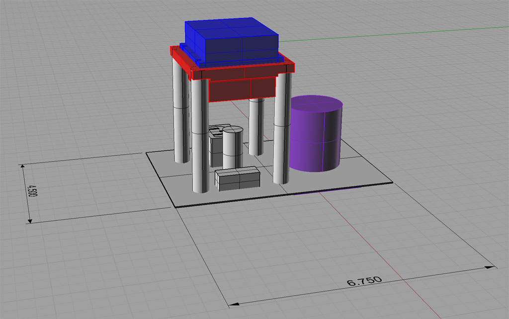
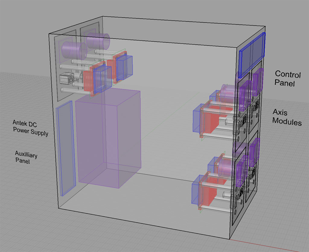
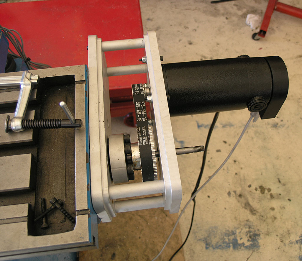
Next steps are to finalize my breadboarded wiring, clean it up a bit with cable ties and such, wire the other 2 axis modules and test them, and then assemble all this into the enclosure NEMA box and test it all again. At the conclusion of all that, the servos go on the mill and we'll see about some real fun!

Cheers,

BW
 
Got the last of the axis modules wired and tested today. So now, I've had servo motors walking around on the wife's carpets. They go really fast and are almost silent compared to the steppers I'm more used to. Lots and lots of torque too. They seem almost more like small spindle motors than anything. These are 850 oz in servos rated for about 650W continuous so that's maybe 0.8 HP. They are stout!

Here is a finished axis module:

P1010988.jpg


There are two connections. The heavy wiring goes to busbars for DC ground and the DC servo supply (circa 70V). The DB9 is a quick disconnect. There are essentially 4 signals:

- Step: Move the motor one step. My motor has 2000 steps per revolution, so that tells you the resolution. A step on my mill is 0.000035".

- Direction: Which direction to move in. Clockwise or counterclockwise.

- +5V from the Breakout board. The Gecko servo drive wants to see this as a reference, and so calls it "Common". I personally found that confusing and initially tried to hook it to ground with no end of troubles until I figured it out.

- Error/Reset: As we've discussed in other threads, the servos will throw a red flag if the computer tells them to move and the encoder sees that they didn't move within a certain tolerance of the desired amount. This signal communicates that condition back to the rest of the system and stops the machine.

I have several kinds of fault on my system including servo faults, Emergency Stop (initiated by the operator when he sees something terrible to behold), and what's called a "safety charge pump". The latter is a sort of heartbeat the PC sends out so that if the PC should crash (you gotta love Windows!), it will stop sending the heartbeat and the machine will stop.

What's next?

The electronics are basically done. I need to finish up the enclosure box, get everything mounted in there, and test again to be sure I didn't screw it up. I am hopeful that can be accomplished this weekend, or most of it.

After that, I need to install the servos on the mill and see how well it does slewing the axes around.

Cheers,

BW
 
Bob, this is an awesome thread. I love the idea of CNC but don't have a clue about the install or operational/programming details. Thanks for starting to detailed the process. Looking forward to more.
 
Are you using the 3 prong plug to carry the power to the servo motor? I would be very careful with that, since that is a normal plug for 120vac. If someone were to take a common PC power cord and plug it into that your Gecko would be fired.

Years ago a friend wired his new, very expensive, hi-fi speakers with common power plugs. One day his wife picked up the wrong plug and plugged his speaker into the wall. Vary sad.

I know they are cheap and easy to get, but it scares me.
 
Yep, they are IES plugs.

There are a lot of ways for the unsuspecting to destroy a CNC machine fooling around with it.

Or, as the software industry likes to say, "Just as soon as you get done idiot-proofing, someone builds a better idiot."

I am more concerned about the possibility the plugs pop out during use than I am about my wife plugging one into the wall. I will be remachining these panels out of 1/4" aluminum once the CNC is running, and at that point I plan to switch to connectors with a positive lock.

I'll probably use microphone connectors. I can just imagine what would happen if the wife or daughter mistakes my CNC mill for a Karaoke machine!

:fan:

I must say I have been extremely pleased with both the CNC4PC boards I've been using and the Gecko servo drives. I have made some pretty interesting wiring mistakes and including one that produced lots of smoke (!) and I've yet to blow up either (me knocks firmly on the nearest wood!). There is a lot of lore on the 'net about what you can and can't do to Geckos, but these little beasts are amazingly resilient.

I even found cases where Mariss suggested doing some of the no-no's as a test. For example, the Gecko instructions and the web lore say that you must positively never ever put a switch or fuse between the Gecko and the servo. The rumor is that if the switch is thrown or the fuse blows, you just bought a new Gecko. This BTW, is a concern for the power cords--they pop out easily and hence threaten the Gecko, right? But, it turns out, that if you search carefully, you'll find a post by Mariss where he suggests testing the Gecko's servo fault circuit by unplugging the motor. If you don't get a fault (I'd call that a fault!), there is a problem with the Gecko. At one point I was plagued by servo faults and so I tried this and sure enough, I discovered that the problem was not with the Gecko as it faulted fine on that example.

There are a lot of fascinating little trouble shooting bits scattered all over the web. It's a great pity Mariss or someone hasn't grouped them all together into a troubleshooting guide as it sure would make a lot of people's lives easier.

BTW, I've traced all of my wiring errors to late night sessions on a work night. This is my second controller, and the first had no such errors, but I did all of it's wiring during a time when I was unemployed. I'm beginning to suspect that wiring up something complicated late at night is not working as well for me as it used to when I was a college kid.

DOH!

Cheers,

BW
 
Another fruitfull weekend of working in the shop has left me a significant step closer. After much fooling around, I have the enclosure mounted to the side of the rolling tool chest, the electronics inside, and they're working, so I have successfully spun all 3 motors (even at the same time, LOL) under Mach 3 computer control. Yay!

Here are a couple of piccys:

P1010993.jpg


P1010990.JPG


Things are a bit messy inside the cabinet for my taste. They reflect the "just get it to run" stage I'm at in the project. I plan to CNC some new panels and when I go to install them I'll convert the rat's nest to proper wiring harnesses. At this stage though I don't always know where a wire is going, and it doesn't always stay there once it arrives! :big:

Next weekend's project will be to get the servos mounted on the machine so I can move the table and milling spindle around. That should be pretty exciting. I need to mount the timing belt pulleys on the servos. My plan there is to use 1/8" roll pins that go through the shaft and pulley. Of course I'll have to machine the hole for them.

Getting substantially closer!

Cheers,

BW
 
that's very interesting and a nice job but i have like many questions when where why how if no really as confusing as it looks was that a kit type of set up or is that your no how type of thing. I would like to try it I have build computers before is it like that you buy the boards and add the items.And where do you buy the parts eBay. thank you for sharing i am watching this I have a maxnc 15 machine that's runs mach3 softare and the learning curve well is very curvy to say the least.
 
artrans, this is somewhere between a kit and know how. By that I mean all those circuit boards were assembled, but I had to figure out how to integrate them together to get the desired result. There is quite a lot more about this on my web site, www.cnccookbook.com.

There are other approaches that are closer to a kit. For example, you could buy a power supply and a Gecko 540 and be pretty nearly there on the electronics side.

But there is definitely lots to learn. None of these parts were bought on eBay, though the power supply is available there from the same manufacturer.

Best,

BW
 
Excellent progress these last two days. I now have the X and Y axes fully powered and running on the mill.

The servos are really not tuned yet, but even in their rough state I was able to move the table at 180 IPM! I am not suggesting that is something that will be accurate or even usable, it was just play, but it was fun! I tried for 200 IPM, but the servos started faulting again and I didn't want to spend too much time tuning for a scenario that isn't real anyway. The recommended setting others are using for this mill is more like 100-120 IPM.

The biggest challenge to this stage wasn't really so challenging, I had to drill timing pulleys and shafts for roll pins to mount the timing belt pulleys, and I had to slightly adapt the IH brackets for these new servos.

Here are the two axes:

P1011009.JPG


P1011008.JPG


My next problem is adapting the fit of the Z-axis:

P1011010.JPG


I love the HomeshopCNC servos for their performance, but the shafts are sure short for the IH CNC kit!

If you want the full blow-by-blow of how I set up the roll pins and other work on these axes, check this page for details:

http://www.cnccookbook.com/CCMillCNCServos.html

Cheers,

BW
 
Hey Bob - I love the conversion. I am wondering why the motors are geared down so much. Most of the direct coupled stepper systems use around 400 0z-in motors. You are using around 800 oz-in servos and gearing down by what looks like abour 3:1 giving about 2400 oz-in torque to the lead screws (I am just guessing about the ratio). Can you help me understand why? Thanks.
 

Latest posts

Back
Top