Help machining a groove

Home Model Engine Machinist Forum

Help Support Home Model Engine Machinist Forum:

This site may earn a commission from merchant affiliate links, including eBay, Amazon, and others.

barryb

Member
Joined
Feb 20, 2011
Messages
6
Reaction score
0
Hi

Not sure if this is the right place to ask this question, please correct me if I am wrong.

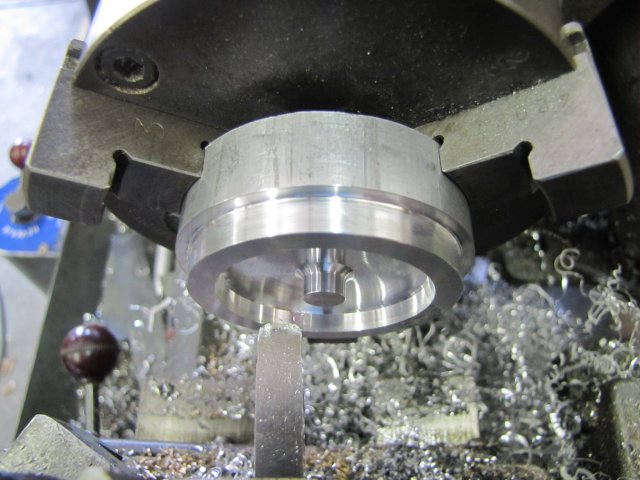
I am fairly new to model building and have a problem machining the flywheel of my first model (see attached drawing). What is the best way to turn the 10mm wide groove each side if the flywheel especially the right side, the other side I guess I could get in with my 6mm boring bar. Any help woud be greatly appreciated.

Barry

View attachment V13-3.bmp
 
well, not sure if it help, but if i have to machine a piece like this i just cut the center hole first, then mount a shaft in the lathe that fit the hole an put the piece in the middle of the shaft with a locking screw (the other extreme of the shaft in the live center), im not sure if i say it right, but with that setup i should be able to machine the two faces with right and left hand cutting tools, that way you don't lose concentricity fliping the piece in the chuck for machine the other face ::)

other way is to carrefully make the flip in the cuck, i recomend a four jaw chuck because you can ajust the ofcenter, and with a dial indicator set the face and sides true to ensure concentricity

other solution is to machine the groove in a rotary table on the mill (i dont get one yet, but im sure that a end mill will do the job easy)

hope to help

Saludos!
 
Actually one more piece of info would help here. Is this a casting or are you machining it from bar stock?

If it's a casting, I would turn it on an arbor afrer boring the center hole.

Bar stock made I would make it long so as to ba able to turn it in the chuck once one side is done. Once the second side is done you just face it to length.

The easiest of all is the rotary table and chuck in a milling machine.

I am sure others do it differently and that's what makes this hobby interesting. Hope this helps.

Did you find the "Unit Converter OK"

"Bill Gruby"
 
Hi

Thanks for the replies, now I have some ideas. I am turning it from 65mm bar stock and intend to face one side then reverse it in the chuck. Turn down the 21mm end and add the recess, then drill and bore the centre to 12mm. I will then reverse the piece in the chuck and turn to the correct length and add the other recess. I will then fix the crankshaft to the flywheel and then holding the crankshaft in a collet chuck, true up the outer diameter giving it all a final polish. Does this sound like a plan. Attached is the final assembly diagram.

Bill .. the problem that I was having converting using a calculator is the build up of tolerances when you have to round up/down. I guess this will come with experience and sorting the problems during the build as they arise

Barry

View attachment V13-13.bmp
 
Hi Barry, and welcome to HMEM!

This is the correct place to ask questions Thm:

Your machining steps sounds good; there are a couple of ways of doing it, but you definitely have a plan.

As to converting all the dimensions - this initially intimidated me a bit as well when I started out; now it does not even bother me any more...
So some tips that worked for me:

Get a small scientific calculator to keep in your shop; it's really handy all the time.

When converting plans, and if you want to stay true to the original imperial dimensions, store 25.4 to the calculator's memory. This makes it quick to do the conversions. Start with the fraction and divide it up. If it's more than 1" like 1 1/8", add the whole number of inches, and then multiply with memory recall - e.g. 1 1/8" : on the calculator do "1 divide by 8 equal plus 1 equal times RM equals". Round your values to 0.01mm; that is in 98% of cases close enough. Try and work from the plans so that you have a reference point for incremental values, and work with the total distance from the reference point; this minimizes the effect of cumulative errors. Once you've done two or three plans like this it gets a lot easier.
Having said that, it's the harder way of converting plans - though I've found great benefit in doing it that way, as it actually gave me a good feel for how big things are if referenced in imperial by other members.

Easier ways of converting plans - if you don't mind the scale changing a bit - is to use a factor of 24mm = 1" - this will leave your model ever so slightly smaller - or use 32mm = 1" - this will result in a bigger model. There is an advantage to these methods though; for example if a drawing states you need a 1/4" shaft and you use the 24mm=1", it actually ends up as a 6mm shaft; very common to find in metric areas. Simmilar for 1"=32mm; that will result in an 8mm shaft. A lot of rounding issues will "disappear" as well.

I use a combination of the true conversion and the "off-scaling"; I build my models to a true 1" = 25.4mm scale, but then go through the plans again, and convert shaft sizes (and corresponding holes in parts) and so on to the closest appropriate metric equivalent.

The biggest issue I've found with the conversions is fasteners; getting the best equivalent metric for the imperial sizes can be confusing at first. John Bogstandard uploaded a file here that can help a lot with that.

Regards, Arnold
 
If you use CAD you normally have the ability to select alternate measurements. Imp to metric and reverse. Depending on the requested accuracy of the measurements the alternate is picked up without too many problems.

Hope this helps

Best Regards
Bob
 
The sequence I would use is this:

1) Chuck 65mm material and turn the right side portion. Drill and bore the center hole a bit deeper than the plan
2) Chuck the 21mm portion in a collet, part off slightly long, face
3) measure the flywheel rim width, then face to final 15mm and turn to 60mm diameter
4) machine groove
 
Without knowing your lathe, I'd follow what KVOM suggested. To cut the grooves use a right and left hand boring bar to get the square corners. You will need a hefty LH bar as to get in on your right side. Supportin the flywheels with a 12mm crankshaft to cut the grooves would be tough from a chatter point of view, to flimsy. hold the OD or the hub.
 
Hi

Thanks for the pointers KVOM. Yes machine tom you are probably right about turning the lump on a 12mm shaft. About right hand and left hand boring tools. I only have a right hand tool which I was going to use for the outer part of the groove, then I was going to reverse the lathe and cut the inner from the other side if that makes sense. Is this an acceptable method? My lathe is an Aminster BV20M if you guys are familiar with that model, a fairly standard multispeed, 100mm chuck 4 toolpost machine, 100mm swing 350mm between centres. Thanks for now

Barry
 
Rather than a boring par, you can grind a HSS tool with a square flat end and tapered sides for clearance (i.e., trapezoid cross-section).
 
Barry, I had a quick look at our lathe's specifications, and as the chuck does not screw onto the spindle, reverse turning should be fine Thm:

Just a thought - you mentioned you have a right-hand boring tool; and then describe steps used for a left-hand (which would be the normal) boring tool. If it's a bought boring tool, it will most likely be left-hand; right-hand boring tools are a bit scarce.

A caution though - what you will be attempting is in essence a facing operation, and boring bars will be inclined to chatter a lot on a cut like that. I don't know exactly what your cutting tool looks like, but if possible, keep any overhangs off the toolpost as short as possible.

It's little problems like these that prompted me very early on to start grinding up my own toolbits. While the recess shown in your flywheel drawing show square corners, it is common practice to have rounded corners in flywheel recesses. For that, I use a tool like this:

If you click on the image it will load a larger one where the toolbit's profile is more visible. The recess in the center of the cutting face is to minimise chatter.

Regards, Arnold


Barry,

First of all welcome.

There where some comments about metric to english conversions. IMHO, I'd try to stay in the deminsions given on the drawings. It was in recent past that someone couldn't convert correctly between english and metric and we lost a Mars Lander for their screw up.

Depending on how well equiped of a lathe you have (with multiple chucks), I'd do the below differing from KVOM,

1. If you have a horizontal band saw, cut off the round stock you will work save a little extra length for facing.
2. Using a 3 jaw chuck, face off the right side of the flywheel and then drill and bore out the center.
3. Turn and face off the length and rh side of the flywheel.
4. At this point, I'd modify a broken parting tool that is the width of the grove and turn the groove before I remove the part out of the
chuck. A word of caution here, if you remove flywheel out of the chuck before you are done turning the rh side of your
part, you will lose all concentricity in the part if you should try to put the part back into a three jaw chuck and make touch ups.
5. Change chucks to a four jaw chuck, mount the rh side of the part up using thick shims so you don't mar finished surfaces and center the part up using your dial indicator. Or, if you have a collet chuck for you lathe, just mount the finished part in a collet.

Good luck with your project.

George

 
Thanks guys for all your help. All my tools are replaceable tip type, I am not at the stage where I know how to grind my own. Yes my naming of the boring tool was wrong the cutting tip points left, I thought the cutting direction was the way you named it. This gets more embarassing my lack of knowledgejavascript:void(0);. KV6UCM I have a 4 jaw independant chuck so I will take your advice. I have got my supplier to cut the bar to the approximate length ( I got 2 for when I screw up the first one). I may not end up with the exact groove as per plan but I will give it my best shot.

Barry
 

Latest posts

Back
Top