Gland Boss and Nut

Home Model Engine Machinist Forum

Help Support Home Model Engine Machinist Forum:

This site may earn a commission from merchant affiliate links, including eBay, Amazon, and others.

Runner

Well-Known Member
Joined
Feb 10, 2011
Messages
124
Reaction score
17
Hi all,

I have a problem making the gland boss and nut for the cylinders and valve chests. The problem appears to be getting the threads for gland boss and nut perfectly aligned and concentric. This error manifest itself by being unable to position the nut at all settings without having the piston rod or valve rod bind in the gland. I have tried to overcome this by reaming the hole for the rod in the cylinder cover or valve chest with the nut assembled, but as expected this only works for the one position of the nut that reaming occurred. Since I cannot predict the position of the gland nut due to the amount of the gland packing installed I have had to open the hole in the gland nut with a small round file to so that it can be set at any position without the piston or valve rod binding.

I have reconciled this opening of the gland nut by telling myself that if the gland material does its stuff then a small increase in gap between the rod and gland nut isn't going to affect the performance of the steam engine. However, perusing the WIP section it appears that when these parts are being manufactured as to be so straightforward not to receive any particular mention.

Is there any steps or setups that I can use for future manufacture to ensure that these parts are made without the need for opening the gland nut hole?

Thanks in advance,

Brian
 
Reaming the parts together seemed like a good idea but threads do not self align very well unless made very accurately. It seems that just using a nut is a poor design and not the way it was done on the prototype. The prototype solution requires the use of very small screws so that puts people off. I have seen one design where the nut screws on the outside of the boss like a collet nut. The nut bears on a bush that fits in a bore in the cylinder/steam chest and compresses the stuffing. Concentricity is pretty much guaranteed with that design. I am glad you asked the question as it has made me reconsider the design of my current project ;D

Jan
 
Hi Brian, like Jan mentioned the threads must be very concentric.

The ideal way would be to single-point turn the threads in both the boss and on the packing nut - but many people seem to have a fear of single-point threading, or are simply not equipped to do it while making them. In some cases, myself included, its pure lazyness, as I'm quite comfortable doing single point threading.

I don't think there's anything wrong with making the hole in the nut slightly over-size; in fact, I do this as a matter of fact - drilling the hole 0.5mm 0.05mm (.002") oversize and I don't even bother to ream the hole in the nut.

The main thing is to get the treading and drilling/reaming for the boss and pack nut done in a single operation for each of the parts (in other words, make the boss on it's own in one operation and make the nut on it's own in another operation). If either of the parts have to be moved during it's machining operation, things will not align properly, unless you spend an inordinate amount of time re-locating it.

To thread the boss, I simply tap it using the appropriate tap chucked up in the drill chuck/collet chuck right after drilling and reaming it. For the nut, I use tailstock mounted die holders to ensure as straight an engagement of the thread as possible. This gives me good results, and I haven't had problems with the pack nuts.

Drilling and reaming them as a pair will most likely not work too well; if the nut's threaded end bottoms out in the boss, it will go slightly crooked as the free play in the threads are taken up. If the nut shoulder presses up against the boss (and assuming you had made a suitable under-cut for thread run-out on the nut) it still might not be entirely aligned - because of concentric free play in the threads. A nut without thread run-out undercut will also go crooked as the thread bottoms out.

Just my 2 cents :)

Kind regards, Arnold
 
arnoldb said:
I don't think there's anything wrong with making the hole in the nut slightly over-size; in fact, I do this as a matter of fact - drilling the hole 0.5mm (.002") oversize and I don't even bother to ream the hole in the nut.

I reckon that's 0.020" - not that it's a problem, the packing is forced against the shaft at the bottom of the gland nut and IMHO 0.010" clearance is neither here nor there.

Best Regards
Bob
 
::) Whoops - sorry; my bad; It should have been 0.05mm not 0.5mm - I got the imperial bit right... You blokes might just end up converting me to imperial still ;)

Edited the previous post to correct it.

Kind regards, Arnold
 
Thanks Jan, I have seen the two screws version of the gland on larger models, however the size I am making it would be difficult to make and the screws would be very small. I haven't seen the collet type of gland nut before, if with your CAD skills you are able to provide a sketch I would be appreciative.

Thanks Arnold that's a bit more than 2 cents worth. I had to look up "single point turning", I assume that it relates exclusively to thread cutting in the lathe. However I use taps and dies for the parts. I use a tail stock drill chuck to hold the tap to thread the gland boss and a tail stock mounted die holder to thread the gland nut. Both operations the lathe is turned by hand. Of course the threading operations for both parts are done without removing them from the chuck after turning/drilling operations.

Thanks Bob for the assurance that 0.010" is neither here nor there, that's nearer my clearance.

I have since been told that I should have used a pilot tap????? This I assume is a tap with a lead-in the same size as the hole so the threads are started exactly concentric and then finished off with a normal tap. Any thoughts?

Brian
 
While you can use a pilot tap I've found that you can mix making the hole a little oversize in both gland and nut and start tapping the gland with the longest taper tap you have then work down to a bottoming tap or the finish. The nut is still best single pointed to be axial with the passage and most folks are happier cutting an outside thread than an inside blind thread.
 
I agree that the hole in the nut does not have to be anything like a close fit on the spindle - just keep opening it out in small increments until it all works.
 
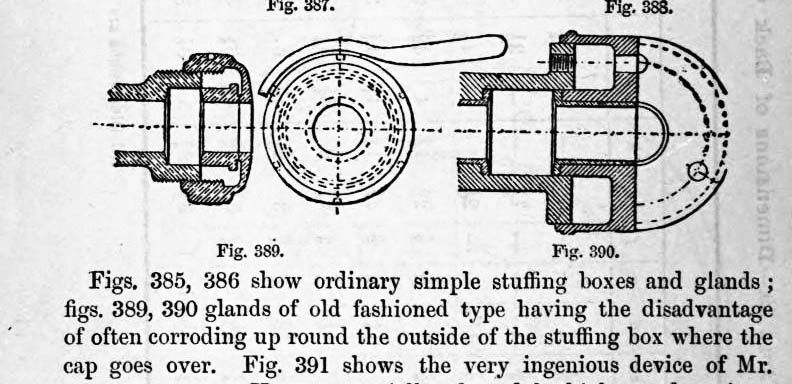
Brian here is an illustration of the gland type I mentioned.

CapGland.jpg


The screw fixing glands are not so bad for screw size, M2 being typical for a small engine. It is more of a fiddle to make but that suits my way of looking at things :)

Jan
 
Thanks Jan for the information. I assume that the insert that presses on the gland material floats so that when the collet type nut is screwed in it self aligns with the rod. The wall thickness of the collet that bears on the rod is small compared to the usual type of threaded nut so the chances of binding are much reduced.

Thanks rkepler, yes I could manage single point turning the outside thread, but not the inside thread. My future attempts I shall use ME threads which are greater TPIs than those I have used in the past. I don't know if that will ease things, but being a finer thread I think that it will.

Thanks Tel, your experience in building the Simplex Locomotive shows me that your comment stems from knowing where and how much freeing up can be done.

Brian.
 
Back
Top