Fancy Vertical Engine 3X size

Home Model Engine Machinist Forum

Help Support Home Model Engine Machinist Forum:

This site may earn a commission from merchant affiliate links, including eBay, Amazon, and others.

toolznthings

Project of the Month Winner
Joined
Dec 11, 2013
Messages
259
Reaction score
183
Location
Ohio
Hi All,

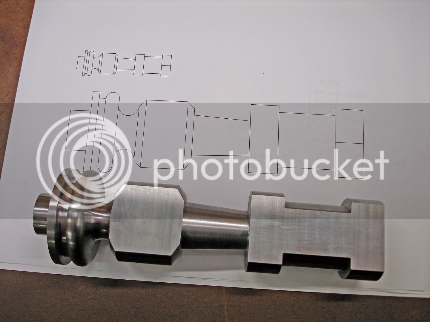
Started another build with a scaled up version of the Fancy Vertical. I increased the size by a scale of three times which makes the overall height with the base about 8 1/2" tall. The crank shaft axle and the wrist pin were sized to .500 and .250 instead of .562 and .281. The air passages were drilled to 1/8". Everything else worked out at the 3x scaling.

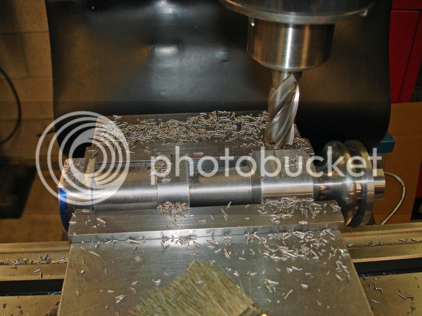
The main body was turned from 1144 stressproof with the largest diameter being 2.250" diameter. After completing the lathe work I rough milled the flat on the body leaving grind stock.


I made a setup with a vise on the surface grinder to finish the flat on the body.
This left me with a smooth and flat surface for the cylinder


The finished flat on the main body .....
 
Beautiful work as always Brian! I will be following along.

Scott

(Ps I ordered the Tormach SBL )
 
Continue to work on main body......
The next operation will be boring for the crank shaft bearing. Set up on the flat face with the hole location established and rough drilled.


Set up the boring head and bored the hole through. Originally was planning on using a couple of needle roller bearings I had, but decided on making a brass bearing instead. The finished hole size is .688 diameter.


Made a setup to cut the flat at the base for the flywheel clearance.
The holes for the air ports will be done later on after the cylinder is made.


At this point in the construction I needed to make the base to support the body while working on the other parts. The base is aluminum and is 3/4" thick and is a octagon 6" across the flats. Rough sawed to shape and setup in the manual mill to bore thru to match the extension on the body. Two 1/8" dowel pin holes were added for location ( only drilled 3/8" deep ) and to prevent movement when doing the outside milling at the cnc mill.


Mounted to a fixture plate at the mill using the dowels and indicated in for 0,0
location. A strap clamp and bolt added to hold the plate for milling.


Milling the outside contour to size .....


Finished base. A set screw hole will be added later to secure the body to the base.

 
The crank shaft machining ......

Surface ground a blank to .468 thick and set up on the manual mill to bore the shaft hole for a press fit of the crank main shaft and a press fit for the wrist pin.
I used a piece of Thompson shaft I had for the main shaft with an overall length of 4-7/32" long. Used this material since it was done and decided not to use the needle bearings. The wrist pin is a standard 1/4" dowel pin 1-1/4" long.
Made a fixture using the two holes in the blank for shoulder bolts. Set up at the cnc for milling the contour.


Some views of the assemble crank shaft in the main body of the engine. The main bearing is installed and a bushing for the cylinder pivot is also in place.
The pivot bearing is recessed for clearance on the backside to provide a counter bore for the spring that will hold the cylinder to the body.

Main bearing turning and thru boring...


In this picture the overall length of the crank axle has not been established. After determining the above posted overall length, two flats for the flywheel set screws were ground at 180 degrees.
 
Decided to do the flywheel for the engine next. Used the scaled up dimensions and added a hub for set screws. Turned the o.d., face, hub o.d. and thru bore in one setup, then finished the opposite side in soft jaws. Tapped for two 10-32 set screws.
Some finish work and paint to complete.


Work on the piston rod and piston next ....
Turned the piston rod diameter from 3/4" brass then setup at the mill in a indexer to mill the flats and thru hole for the crank pin.


The piston was turned leaving stock on the o.d. for final finishing. The rod and piston were then soft soldered together.


Ready for final turning to make the piston and rod concentric. Sorry for the blurry pics. :(


Machining the cylinder from brass bar stock. The finished overall dimension is 3.375" long x 1.500" wide and 1.875" front to back. First operation is to mill the cylinder to the above dimensions.


Setting in v-blocks the corner chamfers were milled next.


Made a setup to bore a hole at the cylinder bore location for indicating at the lathe.


At the lathe with the four jaw chuck I indicated the cylinder using the bored hole from the mill. Also checked run out on the face and along the length.


Bored the cylinder to 1.125 diameter. This is a through bore and a cylinder head will be made later to cap off the bore. Fit between the cylinder and piston is about .001 per side.


From the lathe back to the mill to bore a .375" x .500" deep for a light push fit for the cylinder pivot pin. A 10-32 set screw tapped hole was added from the side to secure the pin.


With the pivot pin in place the cylinder was chucked in the four jaw and the pivot pin was indicated in two positions, at the cylinder body and the end of the pivot rod.


A light facing cut on the face to insure the face is absolutely square to the pin and some under cut around the pin to reduce friction between the cylinder and body. Not pictured, the air passage for the cylinder was drill from the outside
face and the entry hole from drilling was tapped 8-32 to be plugged later. Air passage is 1/8".


Added some decorative cuts with a 1/8" ball end mill. The end of the cylinder was tapped with six 2-56 holes for the cylinder head.

Finished with the piston in place.... ( added oil grooves to the piston )

 
I made a set up with the cylinder and crank shaft mounted in the body to transfer mark the position of the air ports to be drilled in the body. A transfer punch was passed thru the cylinder port and used to mark the port position. The crankshaft was rotated to put the cylinder in its furthest point of travel in each direction.
Working from the pivot bearing so I could document the hole locations for further reference, the pinch marks were picked up with a wiggler point. ( punch marks visible behind indicator )


The ports were drilled 9/64". Inlet and exhaust ports were tapped for air in fitting and exhaust out.


Making the cylinder head from aluminum the holes were drilled after turning with the bulk of the stock remaining for holding in the mill vise. The head was parted off after this operation.


The finish work was done on all the parts before final assembly. The base and body were spray painted with hammer tone paint. Holes for oil were added. Some parts were glass beaded.

 
Everything is perfect. I really love the finish.

How can you provide the matt finish on brass. They seems perfect.

Fatih
 
Hi Fatih,

That finish is done with very fine glass bead blasting. Look for a post from me in " Tips &Tricks " showing the process and some examples on different metals.
Need more help let me know.

Brian
 
Good day to be in the shop, 45 degrees and raining today. Final assembly of the parts. Starting with the body mounted to the base. A set screw thru the base secures the body.


The crank in place with the flats for the flywheel set screws. Not sure why the black paint photographs ugly. :eek: It is better than the photos.


The cylinder and the crank with the connecting rod must be slid in place as a unit. Applied a little oil on the cylinder face and shafts. Attached the flywheel leaving some side to side clearance. The connecting rod self centers on the crank pin.


The spring and split collar are installed on the pivot pin with a best guess on the spring tension to start.


The cylinder head with the 2-56 SHCS is mounted to the cylinder.


A view of the air inlet fitting I use on all my engines. Fits a air brush sprayer hose. Also, the little exhaust fitting.


Some final pictures of the engine with a name tag on the base.


A link to the video of the engine running.....

https://youtu.be/3Twu5r3OcdI

Thanks for all the views, likes and comments !!!
 

Latest posts

Back
Top