Hi all
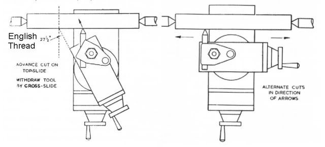
Is there a formula for working out how much the tool will move when the compound is set at a given angle. ie if my compound screw is 10TPi and I have the compound set over at 27.5degrees, how much will the DOC increase with each full revolution of the screw
Thanks
Jim
Is there a formula for working out how much the tool will move when the compound is set at a given angle. ie if my compound screw is 10TPi and I have the compound set over at 27.5degrees, how much will the DOC increase with each full revolution of the screw
Thanks
Jim
")