Building a submarine

Home Model Engine Machinist Forum

Help Support Home Model Engine Machinist Forum:

This site may earn a commission from merchant affiliate links, including eBay, Amazon, and others.

FC4

Member
Joined
Jan 10, 2013
Messages
5
Reaction score
0
Hi all,
I'm in a group of undergrad engineering students who've been given the task of designing and building a 345mm length submarine which runs on a CO2 canister. We have chosen an oscillating CO2 engine as the power-plant and it runs to a prop. We've modeled the initial designs on 3D modelling software but we are having issues on the maths side of things. How can we calculate the rpm of the crank and how can we select appropriate gearing so we get good acceleration but don't effectively do a burnout. Any equations or other help would be gratefully received.
Thanks,
Alex
 
We have chosen an oscillating CO2 engine as the power-plant
IMHO not a good choice got to the Florida Association of Model engineers web site there are plans for various CO2 engines there. an oscillator will drain you tank .


basic power formula (P x L x A x N)/33,000

P= pressure
L= Lengths of stroke
Area of piston
number revolutions per minute
33,000 converts foot lbs per minute to horse power
dimensions are in feet.


Please post an intro when you get a chance.
Tin
 
Don’t forget to divide 33000 by (2 times pi)

If N is radians per minute, then the equation is good. However if N is in rpm, then 33000 should be approximately 5252.

Propeller design is pretty involved. As a starting point, I would recommend going to a boat store and looking at "small" electric trolling motors. Take note of the propeller dimensions (size, pitch, blade count, ect), Also note the DC horsepower rating of the motor, and the rpm in which the propeller is advertized to turn while in operation. This will give you a good idea of the power requirements of a small prop. If you size your CO2 engine to big, you'll cavitate and run out of fuel quickly. If you size your CO2 engine too small, you won't overcome drive-line friction.

How deep, how fast, and how far must the sub move? What size CO2 tank are you going to use? Will you be racing other subs?
 
Hi all,
I'm in a group of undergrad engineering students who've been given the task of designing and building a 345mm length submarine which runs on a CO2 canister. We have chosen an oscillating CO2 engine as the power-plant and it runs to a prop. We've modeled the initial designs on 3D modelling software but we are having issues on the maths side of things. How can we calculate the rpm of the crank and how can we select appropriate gearing so we get good acceleration but don't effectively do a burnout. Any equations or other help would be gratefully received.
Thanks,
Alex

Hi FC4,

I think the engine below is the ticket, you might have to tinker with the equeation from TIN to get your calculations right.

[ame]http://www.youtube.com/watch?v=Jc7LWZQ_ZXM[/ame]

Good luck,,

A.G
 
Don’t forget to divide 33000 by (2 times pi)

If N is radians per minute, then the equation is good. However if N is in rpm, then 33000 should be approximately 5252.

Propeller design is pretty involved. As a starting point, I would recommend going to a boat store and looking at "small" electric trolling motors. Take note of the propeller dimensions (size, pitch, blade count, ect), Also note the DC horsepower rating of the motor, and the rpm in which the propeller is advertized to turn while in operation. This will give you a good idea of the power requirements of a small prop. If you size your CO2 engine to big, you'll cavitate and run out of fuel quickly. If you size your CO2 engine too small, you won't overcome drive-line friction.

How deep, how fast, and how far must the sub move? What size CO2 tank are you going to use? Will you be racing other subs?

Entropy,

The OP said the design will be 345 mm or just under 14 inches... ergo the co2 tank will likely be small, as will the prop requirements. This will ultimately lead to the appropriate engine size.

Their best bet is to look at existing model props, especially those designed to provide good propulsion at low rpm. Raboesch model 174 4 blade prop would be best.

They are designed to run at lower rpm which would conserve their co2 supply.
 
Way back when I was a teenager, I built a small battery powered boat. I had no access to a prop, so I built one. It was built using a drill press, tin snips, file and soldering iron. It was way too large, so I built another one, then modified it's pitch. They are really easy to make. Maybe not as refined and efficient as a commercial unit, but way better than a gearbox.

I think you will find that building an engine, then customizing the prop for the application will be the easiest out. For sure it would be the quickest way to approximate the final prop, be it shop made or commercial.

While the wobbler may not be the most efficient choice, considering size of your project and the complexity of alternates, I think overall ,it would be a good choice. That last thing you need is a powerplant that will take a year to complete.

Bill
 
Perhaps FC4 will tell us the metrics that will be used to evaluate their project?

Will it be endurance, max speed, etc. Has a CO2 tank capacity been prescribed for the project or is this open to the constraints of the overall sub size?

Engine, prop design and gearing if any should be based on the metrics to be used to evaluate the project... i.e. if it is endurance or speed, i'd select a good commercially available prop design for the task that has proven engineering and manufacturing. Then i'd find the best multi-cylinder oscillating engine design that I can find.. modify the design to provide suitable power output.

I'd then find the max efficiency range of the motor, and try to run the motor in that range while under full load. Then I'd calculate any necessary gearing needed to bring the prop rpm into the correct range for max efficiency of the prop design.

I'd regulate the CO2 to the engine using a pressure regulator to drive the engine at the rpm that provides the max efficiency of the engine design. I'd use a 42g disposable CO2 cartridge which has a thread to accept a standard or custom pressure regulator.
 
Last edited:
Compressed CO2 might be difficult to use as when released through the motor there are going to be problems with bouyancy as the gas will expand into the hull. There are plenty of model submarines about but as far as i know they all use elecric motors for motive power.

Cheers
John
 
The sub can be designed for automatic buoyancy compensation sort of like a buoyancy vest for scuba diving. A through hull fitting attached to a pressure release valve can vent the CO2 exhaust in order to maintain a standard hull pressure which minimizes impact of expanding CO2 gas within the hull.

Initial neutral buoyancy and subsequent sink and rise can be implemented using water ballast only.

Damn this thread makes the boat builder in me want to build a sub...
 
there are going to be problems with bouyancy as the gas will expand into the hull.

As long as the gas doesn't blow up the hull or disposes water in the hull, nothing will happen.


Nick
 
Nick given the small design, and I'd expect the desire to keep the design as light as possible, breaching the hull integrity is a very real possibility...
 
and I'd expect the desire to keep the design as light as possible,

Looking at U-boats, I don't have the impression that they are as light as possible. They are as heavy as possible. Just light enough so they swim.


Nick
 
Ah, but this isn't a real U-boat which has to resist tons of pressure due to deep depths, or implosions of depth charges...

Secondly, they have the design constraints, either self imposed or by their prof that it is to be 345mm long, use CO2 power, and have an inefficient oscillating engine. Those constraints alone dictate a very light design if it is to function as a sub and not some aquarium fixture at the bottom of a tank.
 
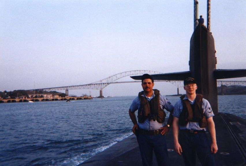
me3.jpg


I served 8 years in the US Navy on Submarines. (I’m the guy on the right).

My boat displaced about 20,000 tons submerged.

Most submarines require lead ballast. The lead serves two purposes – one, permitting the boat to submerge, and more importantly two, to keep the “top-side” of boat in the upright position. Trust me - you don’t want to be within a round cylindrical object during a high sea-state, unless you’ve got a lot of mass keeping the keel at 6 o'clock position.

Air has a density of about 0.0000431 pounds per cubic inch.
Steel has a density of about 0.284 pounds per cubic inch.
Lead has a density of about 0.410 pounds per cubic inch.
Water has a density of about 0.037 pounds per cubic inch.

The design goal for all submarines is neutral buoyancy (so you don’t pop up to the surface, or sink to the bottom, when you lose propulsion). Thus one design goal for this model submarine should also be to have a neutral buoyancy (an overall density approaching that of water). I.E. the sum of the masses of air, steel, brass, copper, bronze, lead, etc that makeup the submarine, divided by the volume of water displaced by the submarine, should equal about 0.037 pounds per cubic inch. This will ensure the ability to submerge the boat without having to use a lot of power to hold it under, or to keep it off of the bottom.
 
Thanks for the rapid responses. I should have included more specs in my question- my bad
16 gram cylinder of liquid CO2- energy source
The purpose of the craft is to beat all rivals in a 10 metre sprint in a shallow tank: economy only needs to be considered in the sense that we shouldn't run out of CO2 too early.
Alex
 
Great information Entropy...

It also helps make my point, since given the typical hull shape of a sub, basically a somewhat distorted prolate spheroid... with the bow being tending to be more bulbous than the stern which is more tapered ... I calculate the volume to be ~ 90 cubic inches for a 13.58" x 4" beam sub of the typical hull.

I have done a very similar exercise many times in the past having designed model blimps and calculated the volume of helium and lifting capability of the envelop... even more critical than subs.

Given the density of water we have a displacement of ~3.33 lbs. To achieve neutral buoyancy the hull and entire contents should total 3.33 lbs.

So very light design and materials required... the weight of the engine, CO2, prop, shafting, regulator and CO2 cartridge will eat up a lot of that allowance already... and hopefully RC gear.
 
FC4,

Okay, well I dont think you will run out of fuel no matter how inefficient your engine....

16 grams liquid CO2 will yield ~488 cubic inches of gas at standard temp and pressure (30.5 cubic inches gas per gram). I say approximately because the filling of standard cartridges is somewhat inaccurate.

Given typical oscillating twin engine (.5 bore, .62 stroke running perhaps as high as 1000 rpm) should run for ~2 minutes on that charge. Plenty of time to cover the distance of 10 meters.

I have a spreadsheet which adjusts the run time based on engine bore, stroke and rpm if you want to explore the variables. I am not familiar enough with the theoretical maximum rpm for oscillating engines myself... but maybe someone else here can add that. I'd design for the largest bore and stroke that can fit within the hull and remain below the design displacement...

As an aside, given the design goal I'd use a a system that would guarantee I'd achieve the maximum theoretical hull velocity given the drag coefficient of your hull design - therefore I'd use a steam turbine directly coupled to a 45 mm 6 blade prop like the one here. I'd control the rpm via gas regulator and shoot for 9000 rpm and use utilize every last drop of fuel... with an oscillating engine you will not likely use all your fuel.

image003.gif
 
Don’t forget to divide 33000 by (2 times pi)

If N is radians per minute, then the equation is good. However if N is in rpm, then 33000 should be approximately 5252.

Nope do not worry about that not needed

basic power formula (P x L x A x N)/33,000

P= pressure at the piston or enginge intake
L= Lengths of stroke in feet
Area of piston in ft^2
number of stokes per minute. (not rpm) similar but accounts for multiple strokes per revolution.
33,000 converts foot lbs per minute to horse power
dimensions are in feet.

If you use an engine designed for steam or air you need a regulator. If you use a co2 engine design you do not need a regulator.

Tin
 
CO2 engines have a momentary open valve and are designed for the relatively high pressure of the co2.

Oscillatory are nice and easy to make but the valve design is inherently inefficient.
Tin
 
Back
Top