Bevel gears ?

Home Model Engine Machinist Forum

Help Support Home Model Engine Machinist Forum:

This site may earn a commission from merchant affiliate links, including eBay, Amazon, and others.

picclock

Well-Known Member
Joined
Dec 17, 2010
Messages
262
Reaction score
3
I need a pair of bevel gears for 1:1 right angle drive to operate an inlet valve. Sadly I have no idea how to manufacture same. I have a lathe and mill but the way I see it I think you would need a shaper to make these. I looked up prices to buy ready made and needed to sit down after the shock :eek:. I considered getting a pair of brass mechano gears off of flea bay but would prefer steel, and am uncertain of the condition.

So several questions really. Is it possible to make these with the equipment I have, or can I scrounge these off of some obsolete or scrap gear, or is there a reasonably priced supplier in the UK someone can point me at.


Best Regards

picclock
 
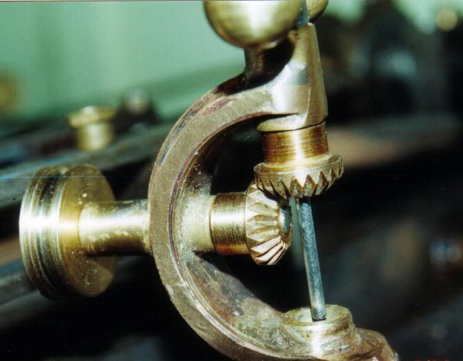
You can do then in the lathe, racking the topslide back and forth in imitation of a shaper.

I did this pair for a governor just that way on the Myford - OD is about 0.375"

rvgov2.jpg
 
picclock said:
I need a pair of bevel gears for 1:1 right angle drive to operate an inlet valve. Sadly I have no idea how to manufacture same. I have a lathe and mill but the way I see it I think you would need a shaper to make these. I looked up prices to buy ready made and needed to sit down after the shock :eek:. I considered getting a pair of brass mechano gears off of flea bay but would prefer steel, and am uncertain of the condition.

So several questions really. Is it possible to make these with the equipment I have, or can I scrounge these off of some obsolete or scrap gear, or is there a reasonably priced supplier in the UK someone can point me at.


Best Regards

picclock

Hi,

You need a mill, a rotary table or an indexing head , a suitable gear cutter for the module or DP of the gears you need or you could make a cutter if you want . I am a novice and have managed to cut Aluminium spur gears using a home made cutter, it is a rather involved buiness but certainly possible to do it. Alternatively you could google motionco, they seem to have some ready for despatch small plastic gears in stock and they are UK based.

Good luck,

Regards,

A.G
 
No need for all, or any of that stuff - just the lathe with a swivelling top slide, a ground up hss tool set on its side and go to it.

 
You could make something that will work but it will not be a true bevel gear.
The DP varies from the outer diameter to the inner and this cannot simply be cut by planing , milling or any straight forward means.
This link will take you to an early patent for a bevel gear cutting machine.
http://www.google.com/patents/about?id=n6diAAAAEBAJ&dq=294844
To produce the correct involute tooth form requires complex movement of the gear blank during the machining operation.
 
@ bogstandard

Many thanks for the info. That's a neat way of doing it, although the problem I forsee is with filing the last inside part of the teeth, however seeing the diagram of the tooth cutting makes me think it should be easily do able. The nice thing about making one's own is that the size and number of teeth etc. can be optimised for the design, rather than the design be optimised for the available teeth. I think I've sold myself on this way, plus its a good excuse to get an involute cutter ;D

best regards

picclock
 
Many many bevel gears were made using milling machines during WWII and most of them by the fairer sex, having jumped in to fill the gap, whilst the not so fair sex were busy shooting at each other.

They are known as parallel depth bevel gears.

You get the same type of bevel gear using tel's method with the lathe.

The best thing IMHO would be to get hold of a copy of "Gears and Gear Cutting" by Ivan Law, ISBN 0-85242-911-8.

Hope this helps

Best Regards
Bob
 
Tel,

Your way is how a lot of people did it in the past, those that had lathes that could be indexable. My old Atlas was perfect for doing such things.

Nowadays, myself included, modern lathes don't have that feature readily available, and requires a fair bit of work to get it up and running, but most people that have a mill, usually have some method of indexing.

A lot of these old ways of doing things are now being transfered over from lathe to the mill, and in my case, I am doing about 80% of my lathe specialist work on the mill now, because I have to.

So I don't think there is any right or wrong way, just different methods that can be used on different specified machines.


John
 
Kozo Hiraoka's book "Building the Climax" From Live Steam Press has a very detailed segment on cutting bevel gears. This includes making/hardening the gear cutter, blank gear-holding jigs and the actual cutting of the gears using a lathe.

Was able to have a look at a friend's copy but an inter-library loan might be a consideration.

The usual: I am not associated with Village Press, Live Steam, etc -simply a satisfied reader.
 
The gears described in Kozo's Climax book are skew parallel depth bevel gears. In other words the shafts do not lie in the same plane. This is a more complex form of a parallel bevel gear but the information still can be used only the shaft off set is reduced to zero for miter gears with shafts on the same plane.

I think the explanation in Ivan Law's book already mentioned is much simpler and it also explains how to make cutters for the gears.

If anyone is interested in the Bilgram bevel gear generator method that Abby posted the patent link for, there is an article from the American Machinist I transcribed with the drawings in the download section.
http://www.homemodelenginemachinist.com/index.php?action=tpmod;dl=item281

Dan
 
Picklock - as Bogs said there is no right way.

Firstly there is no DP for a bevel gear (other than a nominal central value) as the DP size changes across the face.

Therefore the only "true" way to do this is with a gear shaper.

However taking a nominal DP cutter (or single point - whatever) a good compromise can be achieved using a dividing head set at the root angle and taking 3 passes - one through the middle and two with the head swung slightly - you can of course just opt for the two swung position passes or just the single "through the middle" cut but that won't produce a great result. (the pinacle tooth section will be too thin and the base section too big) you can of course target to get the base section right - but the all points inboard of this are effectively non-runing / cosmetic.

How "true" you need your bevels to be depends on what duty cycle and power transmission for whatever given size.

Like they say - its complicated, but its up to you how far you want to dumb down the process.

2c

Ken

 
Get Ivan Law's book. Repeat: get Ivan Law's book. It's clear and understandable/
 

Latest posts

Back
Top