Advice requested on drawing interpretation

Home Model Engine Machinist Forum

Help Support Home Model Engine Machinist Forum:

This site may earn a commission from merchant affiliate links, including eBay, Amazon, and others.

DickDastardly40

Well-Known Member
Joined
Oct 23, 2007
Messages
309
Reaction score
0
Gents,

I'm in the middle of making the straps at present and I don't think the yokes will present a problem but a further gander at the drawing threw up an anomoly to me:

P1000629.jpg


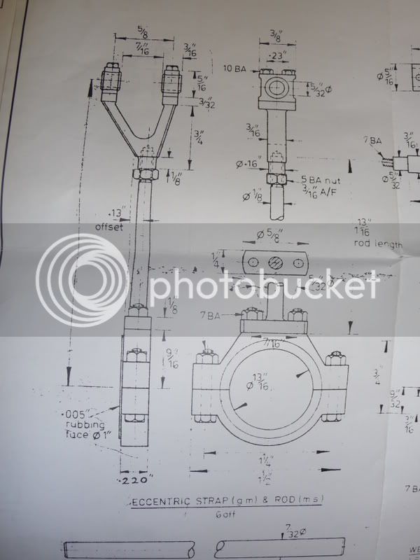
How do you read the offset on the mild steel rod? 0.13"
Off centre along length?
0.13" off centre at the far end ie skewed?

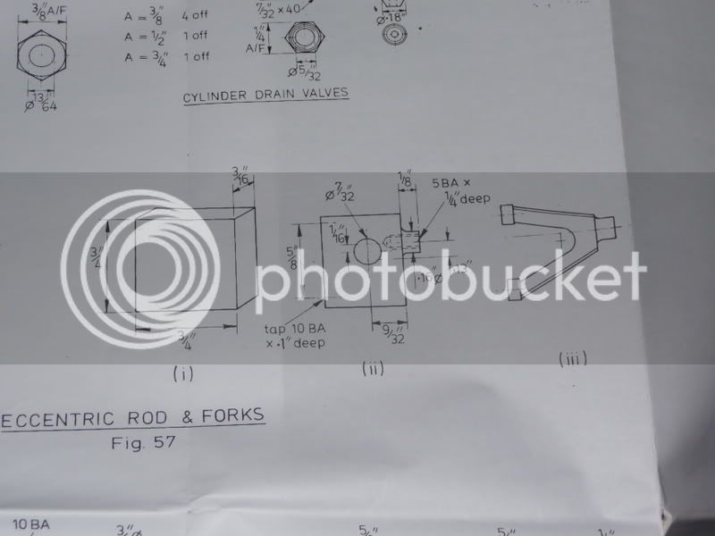
How would you make them? I need 6.
I was gonna turn em from solid and mill the flanges to make the flats.

TIA

Al
 
The way I read it is that the centre line through rod & strap is offset 0.130 from the centre line between the two bearing caps (mid of the 7/16 dimension)

If the offset was dimensioned from both centre lines than I would go with a cranked rod

Its a bit hard to see on the drawing as the fold line distorts the image, best to do a few calculations to see how the two ends align.

Jason
 
I agree with Jason B the whole shaft and eccentric are offset from the centre line of the fork by 0.130".If you look at the drawing and calculate back this would allow for two eccentrics and shafts to be run together from the same journal back to back hence the 0.005" rubbing faces which will bear against each other.

best regards Steve C.
 
There is also an error, the strap is given as 0.220" wide but the mating end of the rod is 1/4" 0.250" ???

Jason
 
Al,

6 eccentrics suggests to me a triple expansion reversing engine.

Below is a picture of full size practice. The ahead rods are concentric and the astern rods are offset allowing both to be run side by side on the journal and operated by the one set of links. So you have only 3 which are offset from the rod centreline.

I hope this helps ??? ???

Best Regards
Bob

Eex.jpg
 
Bob,

Agreed, Most are as you show with an offset yoke, some where made mirror image so fewer spares needed to be carried on board.....6 of one and half dozen of the other.....

I think we need to know why the .220 dimension is needed.....time to check prints I'm afraid....

Dave
 
The .220" looks like a drawing revision as its the only hand written figure.

Its also a bit of a job to work out the overall ctr to ctr length as the 1 13/16 rod length is given but not how far it screws into the yoke. If you are not careful the ctr to ctr lengths could vary by about 0.012 which is around half a turn of 5BA thread. I would make the flat mating surface oversize then once screwed into the yoke make a jig to get them all the same length.

Odd way to dimension the 5/32" thick end of the rod as well

Jason
 
Looks to me that the .220 is an error. The offset to the center of the rod is .13 so if you put two of these side by side it would be .26 center to center when you include the .005 rubbing face on each. It would then seem that minus the rubbing face the rod would be .125 from the outside to its center and thus a .25 width which is consistent with the side view of the mating surface.
 
But teh .130 seems to be taken from the side of the strap not the sid eof the rubbing surface :-\

Jason
 
Glad it wasn't just me that was unsure!

I'm content that the 0.220" dimension is correct as the eccentrics which they sit on (already made) have a thickness before the flange of 0.227 which including the rubbing faces gives a clearance of 0.004"

I'd already seen the difference in flange to strap and was gonna make that flange 0.220" wide.

Maybe time to draw in CAD as suggested. No rush only been over 10 years so far.

Thanks for help so far.

 
Al,

I did a few sums and by my calculation the offset should only be 0.115" and not 0.130" as per drawing. Please check this as I have been wrong before. :-\ :-\

Best Regards
Bob
 
Here is the drawing for the yoke:

P1000630.jpg


It shows the 0.13 offset for the fork as offset from the centre line. I haven't time to draw it to see how a pair match until later.

Thanks for your help so far.
 
Well I have now drawn the yokes several times and cannot get them to look the same as the print.

Does anybody know if it is possible to export an Autocad .dwg file to a viewable method which I can post here to discuss?

Al
 
Invert your screen (i.e. white background, black or dark lines), and then screen capture. Hit "print scrn" button (up by scroll lock), and then open a program like paint. Cntrl-v (paste) the image in. Save it as a .jpg. Post as you would any other image.
 
Back
Top