10K South Bend with horizontal drive

Home Model Engine Machinist Forum

Help Support Home Model Engine Machinist Forum:

This site may earn a commission from merchant affiliate links, including eBay, Amazon, and others.

MarioM

Well-Known Member
Joined
Sep 11, 2011
Messages
83
Reaction score
11
Hi to all.

Does anybody own a 10K SB with horizontal drive like the one in the picture?

south bend 10k.jpg
 
Mario,
I own an undermount drive 10K... (in case any info you want is on parts the two models have in common...)

are you looking into buying one?
 
Actually that is the lathe I own. I like it very much but I find the belt guard is a little heavy.........and sometimes I feel like making a new one but lighter, maybe fiberglass. Any ideas??
 
I've got the gap-bed version, but other than that it appears identical. What do you want to know?
 
My belt guard is thick aluminum, there is nothing wrong with it, it is just the fact that you have to be carefully when you open it and use the lever otherwise you can catch you fingers. Just wanted to share with somebody else that have the same lathe.
 
Now that I know how to put pictures, here are some of my lathe and the belt guard I was talking about.

DSC_6330.jpg


DSC_6333.jpg


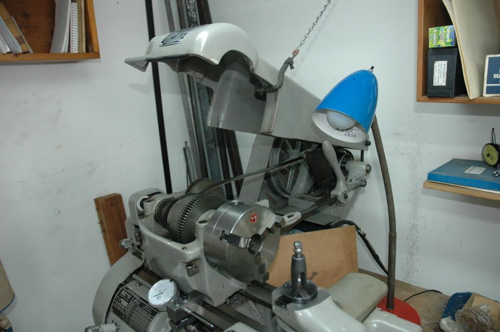
Mine came with a fiberglass belt guard that kept falling down as well as looking like an afterthought. I got rid of it completely and substituted an old-model aluminum guard that covers only the headstock pulleys and flips up out of the way easily. It mounts on the back gear shaft. See photo. The countershaft is well out of reach, anyway, so I have no concern about its lack of a guard.

I also gave up on the belt tensioner. Its design makes it push on the side of the countershaft assembly, making it want to twist. Try as I might, I could never bolt down the countershaft solidly enough so that it would not turn, eventually, because of that side pressure, and mess up the belt tracking. So, I rigged up a lever-operated rod that locks in an over-center position such that it pushes on the center of the countershaft support and the center of the headstock, which I find much more satisfactory, albeit a bit kludgy in design and execution. See photo.

The gear cover, as delivered, was held on with a knurled bolt and a knurled nut which, when removed, released the fiberglass gear cover. Older lathes had a hinged aluminum cover, which seemed better to me, so I decided to put hinges on the fiberglass one. This involved putting a plate on the end of the lathe bed to hold hinges (the end of my lathe bed was already tapped for two machine screws (8-32, maybe??), which made attachment of the plate relatively simple. I made up two of about the simplest hinges imaginable, two short bars of aluminum, the upper one with a fixed pin that slides into a hole in the lower pin. See photos.

To latch the cover I made a standoff of the correct length with a 1/4-20 threaded hole in both ends. The outer end is turned down to fit the existing hole in the cover so when the cover is swung closed the cover fits over the stub. A short 1/4-20 bolt and washer hold the cover closed. See photos. More photos in next post.

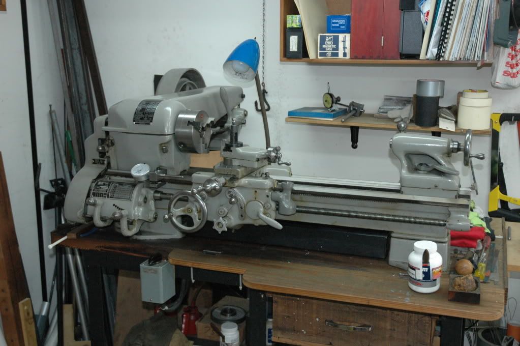
Another thing I've done, which I think I've already described in a previous post somewhere, is slide the headstock about 15" to the right on the lathe bed so it is to the right of of the bed gap. IMO the 10K gap bed design leaves something to be desired, so I've put it outside the section of lathe bed that is being used. Doing so left the tumbler reverse gears exposed, which required making an inelegant but effective cover for them. You can see it in IMG_1803.jpg. If anybody is interested I'll describe how I moved the headstock again.


IMG_1803.JPG


IMG_1805A.jpg


IMG_1806.JPG


IMG_1807A.jpg
 
Thank you very much for you ideas and pictures. It seems SB has a lot of variations in their lathes, as mine also came with aluminum gear cover with hinges, but making a latch is a good idea because sometimes it rattles. At one time I was planning to cut the actual belt cover and put it the same way you put yours but then quit. I think only time will tell.....will use as it is just now and see what happens.
 
I never thought of moving the yardstick over, what a great idea!

I have a 1936 with the four foot bed and the ways are really really worn. If I move the headstock I could use the two feet of ways that still show the original scraping. I can't think of anything longer than that I would ever turn.

Any tips or tricks to move the headstock, or just loosen it and move it to where I want it? The motor is a wall mount so that wouldn't be a problem.

Thanks, Lee
 
The only problem is that you lose the engagement of the headstock gearing with the rest of the gear train on the end of the lathe bed. This is fixable by mounting the stud gear, normally on the headstock, on an extension shaft. This is just visible in IMG_1803, above. Here are some more pictures. The shaft is connected to the headstock with a homemade keyed coupling, and the outboard end is supported by an aluminum block with an Oilite bushing in it. The stud gear goes on the end and engages the gear train.

Probably the most difficult part of the whole thing was making the aluminum block and locating the bushing so the shaft would be properly in line with the headstock.

Note that this will in all likelihood expose the tumbler reverse gears. Be SURE to fabricate a guard for them before using the lathe, as those gears are sitting right up on top ideally located to grab a sleeve or finger.

IMG_1010.JPG


IMG_1013A.jpg


IMG_1014A.jpg


IMG_1015A.jpg
 

Latest posts

Back
Top