A Simple Oscillator (First Project)

Home Model Engine Machinist Forum

Help Support Home Model Engine Machinist Forum:

This site may earn a commission from merchant affiliate links, including eBay, Amazon, and others.

Heffalump

Well-Known Member
Joined
Jan 18, 2014
Messages
75
Reaction score
15
Hiya Chaps,

This is going to be the first thing I've built since college, and I'll be re-learning how to machine as I go along.

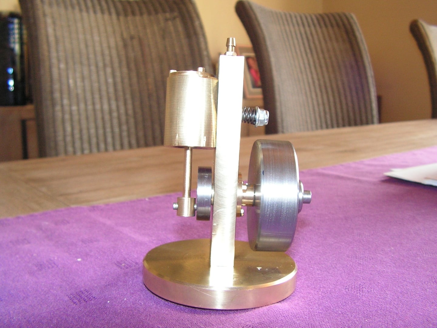
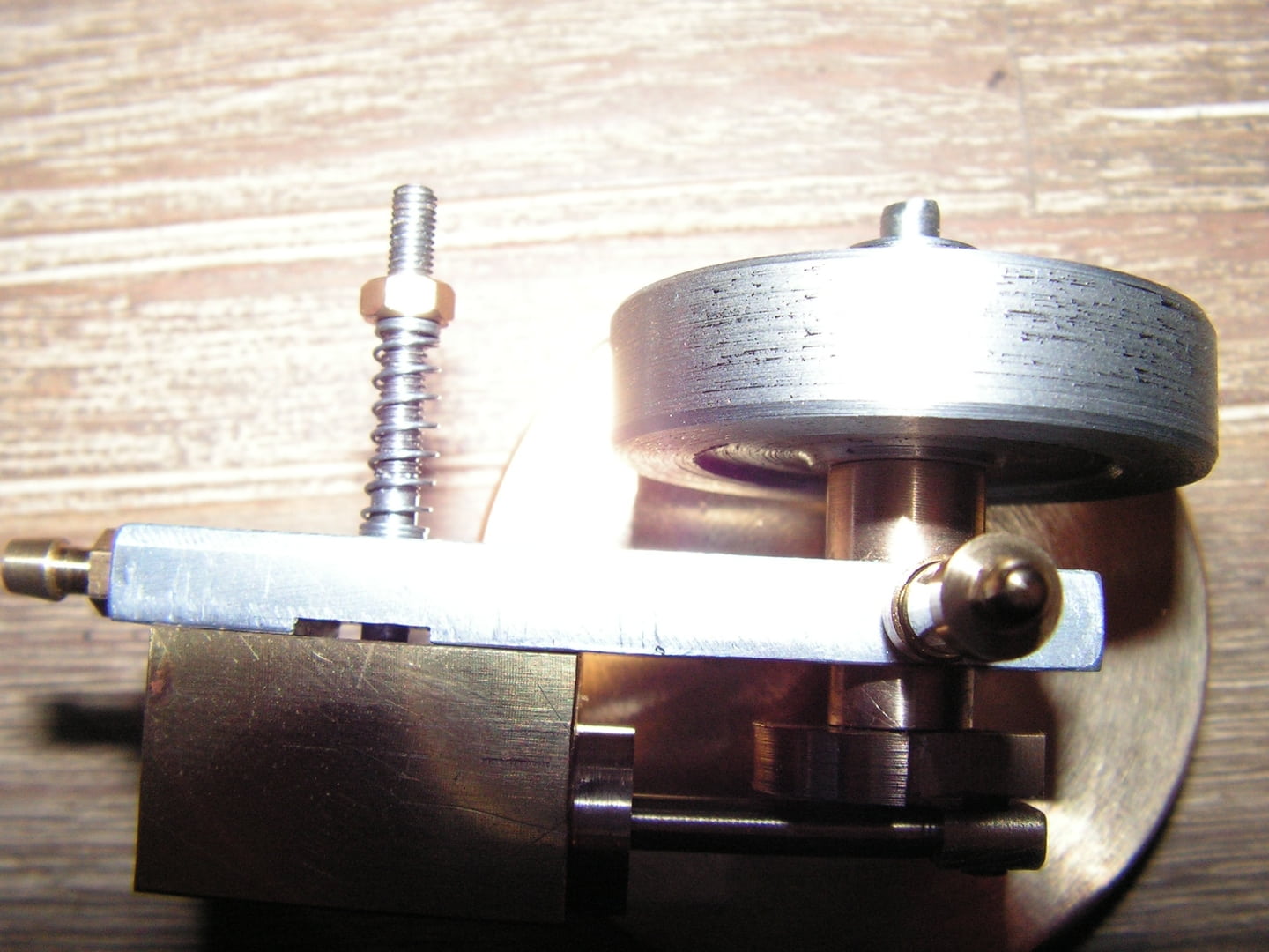
I'm going to be building the simple oscillating engine found here: http://www.steves-workshop.co.uk/steammodels/simpleoscil/simpleoscil.htm

I started first by making the base plate. As this was the least critical part I thought it would be a good one to get my eye in on.

To start with I found a random piece of Ally sheet lying around and got it clamped down on the mill bed.

2w5ivsi.jpg


Here's the blank cut to size

289d56v.jpg


And the stub drill bit set to 0,0 (DRO making life too easy)

2rw0ww2.jpg


Then finally the two holes through which I'll attach the frame.

rwqkqe.jpg


It was fun trying to remember how everything works!

In hindsight, I should have protected the workpiece from the clamps, and I shouldn't have used a file to deburr the edges, so it is quite a messy piece now, but still fit for purpose.

Thanks for looking
 
I started to make the main bearing today.

The plans called for brass or bronze, but I didn't have any to hand, as discussed in another thread I did have some PTFE.

I decided in the end to try with the PTFE as I did have some handy. If it is not fit for purpose in the end I can come back and make another with brass.

I've never used this material before, it's very messy on the lathe!

ir4brm.jpg


I've got the majority of it turned out, tomorrows job will be to finish turning down the back now it's been parted off, centre bore and mounting holes.

5ldr2g.jpg


I'm quite happy with my accuracy so far, I've not used a lathe for 5 years!

fkba01.jpg
 
Always fun to follow a build. Please keep the photos coming.
 
Thanks, it's all going to be little small bits as I am doing this in my lunch times.
 
Didn't have time to upload yesterday's progress! I turned the back of the bearing down, drilled the mounting holes, drilled and reamed the centre and cleaned up the edges a bit.

2lkweh3.jpg


2z894ds.jpg


Then cut the axle to length and cleaned the edges up with the file whilst the chuck was spinning.

Here I made a bit of a mistake. I measured the axle at 6.3mm and the ID of the bearing at 6mm, I thought it would be easier to open out the bearing than try to turn down the axle. I drilled the bearing out to 6.5 (the next drill size I have) and now it's a bit loose.

ju738h.jpg
 
First of many? Excellent choice for a first build. The plans look well laid out with good documentation for each step. My first engine looks like it was bashed out by a caveman with a dull rock. I’ve never used PTFE, but I can’t see that 12mm piston is going to beat up and deforming the bearing much, and if it does, make a new one. Thm:
 
I hope it will be the first of many! I'm lucky enough to be using mostly off-cuts from around the shop at the moment, but I'm worried about the price of materials I'm seeing!

I've been a bit poor at taking photos of my steps over the last few days but here's the evidence, I next turned out the pivot for the cylinder, threaded m4 one end for the thumbwheel, and m3 on the other for attaching to the cylinder.

2vi2lms.jpg


Next I needed to make the pivot nut / thumbwheel

2niwbgj.jpg


And here's the assembly

33za8o5.jpg
 
Heffalump---Nice first engine---But---You'll be sorry. It all starts with a simple oscillator. You will be so excited when it actually takes off and runs on its own that next you'll want to try an engine with a valve---and then when that works a twin----and then when that works, a beam engine.--And after about 10 compressed air engines, you will cross over to the dark side and build your first i.c. engine---and then you'll be wanting to buy better machinery to build bigger models.--Trust me---it's the road to perdition!!!----Brian
 
Hi Brian - thanks! Yes, I fear I will have become hooked, so far I am just enjoying the tinkering time in the workshop, even if my progress is slow (and clumsy). My goal is to build a few boilers to run engines on steam rather than compressed air, if I had the means I'd be building a full size steam engine! I must admit it's the V8 IC engines which drew me to this website, and got me thinking about it to begin with, I definitely want to build an IC at some point..!! I'm quite lucky with the size of the machines in the shop at work. Harrison M250 and a bridgeport series 1.
 
The bits are coming together nicely. Soon, it will be a runner and then, as Brian said........
 
Nice stuff. On hint comment. I was taught to keep a file near the lathe to debur sharp corners. It is a lot easier and faster to do while in the lathe. I even start the parting groove back out the tool take off the bur then finish. just something to add to the note book for next time.
Tin
 
Nice stuff. On hint comment. I was taught to keep a file near the lathe to debur sharp corners. It is a lot easier and faster to do while in the lathe. I even start the parting groove back out the tool take off the bur then finish. just something to add to the note book for next time.
Tin

Thanks for that, It's something I actually picked up over the last couple of days, I've started doing that now, wow it makes life much easier!!
 
Here's some more bits!

Cutting the cylinder down to length

70esuc.jpg


And milling the flat face

ipzadj.jpg


After the exhaust/intake port had been drilled and the pivot mounting hole tapped

1zfmy6c.jpg


Cylinder drilled and reamed, but still needs polishing

29p3nmu.jpg


Mocked up with pivot and thumbwheel

2u53mm0.jpg


There's a lot of tidying / cleaning / deburring to do yet.
 
Hi Jim, your doing a great job there, just thought that I might give you a tip when putting a short thread on a shaft, drill and tap a hole and then put in a screw with a bit of loctite if you wish, then cut the screw to the length required. It allows he thread to be right up to the shoulder. Here's a picture of a M3 thread x 3mm long that I have just done.


Paul.
 
Hi Jim, your doing a great job there, just thought that I might give you a tip when putting a short thread on a shaft, drill and tap a hole and then put in a screw with a bit of loctite if you wish, then cut the screw to the length required. It allows he thread to be right up to the shoulder. Here's a picture of a M3 thread x 3mm long that I have just done.

Paul.

Ohh that's sneaky!! I love this idea - I will definitely be using it next time... Thanks so much
 
I build this one also. Here a picture:

Foto650-4MBUQHMY.jpg


And offcourse a movie:

[ame]http://www.youtube.com/watch?v=2DkUCrBrFug&list=UU1BXeMnWzIagQAC7fKYx0_g&feature=share&index=1[/ame]

Barry
 
  • Like
Reactions: gus
Hi barry, thanks for posting that! it's very enthusing! It's great to see what I'm building, it really seems to have a good rev range, and it seems to run very slowly!
 
A good tip.....In the next picture you will see a other wobbler. You will see that I milled a slot in the middle of the mounting plate..It may be wider.....
But you will see that there is a lot off movement on the top & the bottom off the cilinder. In the middle not much movement. So when the engine runs , you have wear on the bottom & the top , but not in the middle!! Than the air leaks will come.

Foto650-KAKQEM6O.jpg


If somebody want that plan , send me a PB with mail adress...

Barry
 
I haven't posted for a few days - I made a bit of a schoolboy error and ruined my cylinder whilst creating the tapped holes for the cylinder cap. In the end I've now made a new cylinder, which is a much tighter fit on the piston, so I think it's worked out OK.

Milling the new cylinder

j7tcsw.jpg


x5aax.jpg


I think I'm getting better, long bits of swarf = good right?

10okvuf.jpg
 
I keep forgetting to take photos, and I keep making silly errors (including basic maths). Here's some evidence LOL

The cylinder cap now fits snugly on the (new) cylinder

jsyrr7.jpg


The piston didn't fit into the new cylinder, so it was roughed down to size using a file. We seem to have an absence of ALL emery in the shop, so this has gone on my personal shopping list. The file has left the cylinder grooved - which my friend and I thought may help providing a seal with oil caught in the grooves. I don't know if this is misguided or not...

5lxyxx.jpg


Here are most of my mistakes, I started making the frame.

I accidentally drilled the bearing hole 2mm oversize, so I will have to make a collar for the bearing to fit into. Alternatively I could make a new oversize bearing, I'm not sure which to do.

Second event taking me up to TARFUN - the two ports above the pivot are both straight through. However, the intake is meant to be at the top of the frame, this hole should have been drilled blind!! I think I will tap the hole part way, loctite a screw in, and continue as normal. I do not think there is enough clearance next to the exhaust port for a steam / air fitting. What do you think?

2ebd5vm.jpg
 
Back
Top