Threading on Wobbler engine cylinder: first engine-confusion (Brassy Babe)

Home Model Engine Machinist Forum

Help Support Home Model Engine Machinist Forum:

This site may earn a commission from merchant affiliate links, including eBay, Amazon, and others.

mnbylcr2

Active Member
Joined
Jun 2, 2009
Messages
25
Reaction score
0
Hello all

I have started my first build - Dave Goodfellows, Brassy Babe.
http://www.davegoodfellow.com/plans.pdf

I would like a little information regarding how the cylinder actually moves side to side. The plans say to drill and tap so that the hole just breaks into the cylinder but then it says that the screw should jam up before entering the cylinder. Also it says that both the cylinder and the frame should be threaded - but if this is the case then what is the point in the spring on the frame side of the screw. In my understanding, the frame should not be threaded so that the spring is acting to pull the cylinder towards the frame? Is the cylinder actually turning on the threads of the screw?

I`m sorry, I`m sure this is a very simple question, I`m new to machining and certainly to engines and the motion and fastening of the cylinder to frame is causing me some issues.

Many thanks for replies.

mnbylCR2
 
Hi,

As I understand the instructions, you should drill through the cylinder wall, but only tap part way through so the pivot rod jams in tight when screwed in.

On the frame, the tapped holes are for the steam feed and exhaust, not for the pivot, which is a 3/32 inch clearance hole.

Ian
 
Welcome aboard mnbylcr2!

The usual arrangement with oscillators is as you supposed - clearance hole through the frame, threaded port block/cylinder. While I'm not familiar with that particular engine IMHO you'd do best to avoid drilling into the bore of the cylinder - it will create a burr and maybe even distortion that might impede the movement of the piston.

You can always make the port face thicker (and make a corresponding increase in the thickness of the crank/crank disc/big end to keep it all lined up) to give you more 'meat' in which to tap a hole.

This page http://sites.google.com/site/collectedinterests/model-engineering/engines/simple-vertical-oscillator and some of the others on my site might help.

Good luck on your new journey! ;)
 
Thank you for the link and the replys. I am pleased that you would not drill/tap into the cylinder bore and also that the frame would be a clearance hole rather than threaded - these were my exact thoughts.
Has anyone made this engine or can think of any reason why the frame is threaded as well?

I asked this in my original post but no-one has answered it yet - Is the cylinder actually turning from side to side by moving along the threads? I presume this movement will not effect the clearance from the frame and therefore steam inlet: which in essence, brings us back to the spring and clearance hole! - if it was a clearance hole the spring would maintain its pressure pulling the cylinder to the frame/inlet.

This is my first engine and I don`t know whether to go with gut instinct or to follows the plans to detail.

mnbylcr2
 
Hi

Welcome aboard.

True the drawings are a bit vague. The pivot pin must be free to turn in the bore that runs through the frame. If it was threaded the cylinder would move away from the frame causing a steam leak or conversely towards the frame causing it to stop moving. The spring is what keeps the cylinder against the frame and steam tight.

What I have done in the past is put in a cylinder liner of brass tubing inside the cylinder block after drilling and installing the pivot pin. Loctite or soft solder them in. My liners were brass tube bought at a hobby store.

Hope this helps somewhat.

Regards

Ernie J
 
Thanks for clarification regarding the frame. What is the purpose of the liner you mention?

 
The wobblers I have made the threaded hole for the pivot does not break into the cylinder bore. And there is no need to thread the pivot hole in the frame.Tapping shallow blind holes can be tricky.
Shop guys idea of a liner could work well it would eliminate tapping a blind hole wile preventing the pivot hole from entering the bore.
Tin
 
Using a liner allows you to have a cylinder bore that you will not have problems with, as Tin Falcon says trying to tap a very shallow hole and no burrs to remove inside the cylinder bore itself. The finish on the inside of hobby tube is fairly good and for someone starting out will provide a decent cylinder without a lot of finishing. Install a liner and fit your piston to it.

Regards

Ernie J
 
As regards the tapped holes: The holes "A" in the frame are drilled 7/32" for 1/4". This allows them to be tapped 4-20 (although I would tap 4-40 which is more common). Hole "C" is drilled 3/32, which will freely pass the #2 screw body. It is countersunk 11/64" to provide a pocket for the spring.

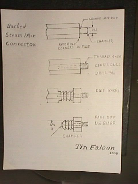
Obviously, having tapped both the inlet and exhaust holes "A", you will want to prepare a short tube for each, threaded #4-whatever on the end. The plans don't seem to provide any instructions for making this tube, so I guess it is left as an exercise for the builder. You need at least one tube since the flexible tubing from your air supply needs something to fit on.

As Dave points out, the inlet is whichever tube you connect to air while the exhaust is the other one, and by switching, you will reverse the direction of the engine.

I agree completely with not drilling through the cylinder side and into the bore. Stop short of that point. You will need to get a 2-56 "bottoming" tap for this hole. A bottoming tap has almost no taper at the point at all and so can cut threads deaper into a blind hole than the common taps do.

Another note about this kind of engine, and in fact, pretty much any single cylinder engine like this. In general it won't self start but will require the builder to spin the flywheel to the point where the piston is on the "out" stroke and the inlet hole is lined up with the inlet from the base which has air applied.

Alan
 
Thanks for all your advice - it has been really helpful and I am glad I asked. I have three other little questions if you could further advise me:

1. Being in the UK, I couldn`t readily find the 4-20 tap and screw and therefore I was going to choose 3mm or 2.5mm. Since I have a M3 tap and screws anyway - I was going to use this. Does anyone see any reason why this would not work and it is critical to use the 4-20?

2. I know quite a few of you have mentioned about using a brass liner for the bore. I have already drilled and reamed my bore and made a piston to fit (I just haven`t yet drilled any other holes in the piston). I am unsure whether to use a liner or not - I would have to remake the piston and redrill the bore in the cylinder. Currently my piston does fit snug into the bore but does feel a touch looser nearer the top - maybe I have a slight taper? How tight should the piston fit into the cylinder? It feels snug, a little on the loose side.

3. Am I correct in saying that the total distance moved in terms of the highest and lowest point of the piston in the cylinder will be the total diameter of the crank?

Thanks

mnbylCR2
 
Also in the UK here :)

1 The size won't matter at all as long as it fits within the available space

2 The fit on these little wobblers isn't critical - they are very forgiving

3 The total distance that the piston will travel is twice the distance from the centre of the crank to the crank pin rather than the diameter of the crank 'disc'

Watch this for a full explanation...

http://www.animatedengines.com/oscillatingsteam.shtml

 
Hey Paul - smashing link! I wish I had seen that earlier when I was trying to figure out what was happening with these engines!

Great stuff - thanks for all the info. I`ll continue to build with this knowledge .... I`ll keep you updated.

mnbylCR2
 

Here is a sketch of how I make 4-40 barb connectors. See the full discussion here

http://www.homemodelenginemachinist.com/index.php?topic=1726.0

MVC-020F.jpg

Hope this helps
Tin
 

mnbylcr2 said:
Thanks for all your advice - it has been really helpful and I am glad I asked. I have three other little questions if you could further advise me:

1. Being in the UK, I couldn`t readily find the 4-20 tap and screw and therefore I was going to choose 3mm or 2.5mm. Since I have a M3 tap and screws anyway - I was going to use this. Does anyone see any reason why this would not work and it is critical to use the 4-20?

2. I know quite a few of you have mentioned about using a brass liner for the bore. I have already drilled and reamed my bore and made a piston to fit (I just haven`t yet drilled any other holes in the piston). I am unsure whether to use a liner or not - I would have to remake the piston and redrill the bore in the cylinder. Currently my piston does fit snug into the bore but does feel a touch looser nearer the top - maybe I have a slight taper? How tight should the piston fit into the cylinder? It feels snug, a little on the loose side.

3. Am I correct in saying that the total distance moved in terms of the highest and lowest point of the piston in the cylinder will be the total diameter of the crank?

Thanks

mnbylCR2

As I said, I would use 4-40, since that's what I have. In your case, you will use what you have or can easily get. Don't forget, though, that the inlet/outlet tubes that you are tapping will need to use a thread diameter and pitch that allows a through hole for the air.

The only reason for a brass liner would be if you couldn't get a reasonably smooth and straight bore. In your case, it sounds like you are doing just fine in that regard and so I'd go with what you have.

One possible way to check your piston fit is: After drilling the steam inlet hole in the cylinder, put a little oil on your piston and drop it down the bore. Now, cover the steam inlet and invert the cylinder. If the piston pretty much stays in there until you uncover the steam hole and then drops out, you have things pretty good for fit.

Alan
 
Do you have a copy of the plans for this. The webiste listed seems to be gone and I'm trying to build it, but only have partial instructions.
 
Back
Top