Air Restriction

Home Model Engine Machinist Forum

Help Support Home Model Engine Machinist Forum:

This site may earn a commission from merchant affiliate links, including eBay, Amazon, and others.

Captain Jerry

Project of the Month Winner!!!
Project of the Month Winner
Joined
Dec 2, 2008
Messages
971
Reaction score
8


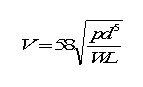
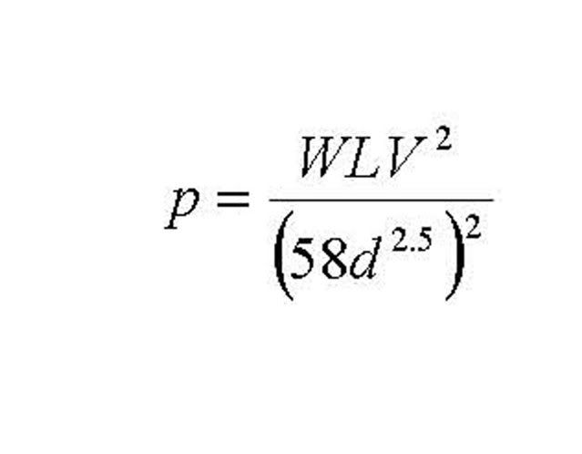
Is there a way to calculate the optimum diameter for an air passage for an air engine?

Assuming a cylinder displacement of .5in and a drilled intake air passage 1 inch long. To run the engine at 40PSI is there a minimum diameter for the passage that will not have excess restriction? And how is it calculated.

Jerry


You ignore friction of the moving air with the pipes and cylinder walls.

Use boyles law of gases, linear expansion of volume with pressure. Calculate the volume of the cylinder. This woud be at 1 atmosphere 3 atm. is about 42 psi so then roughly; air(at 42 psi) could occupy 1/3 the volume it would at 14 psi.

Your passage way should be no less the 1/3 volume of the piston for the pressure.


Rough as 60 grit but very useable,
Kermit


Kermit

Is this what you mean?


Clyinder Displacement = .5cu in
therefore
Passage volume must be .5 / 3 = .167 cu in.

Passage length = 1 in.
therefore diameter = 2 ( sq rt (.167/pi) ) = .461 in diameter!

If I wanted to use 1/8 (.125) dia passage it would have to be 13.6 inches long.

Somehow that doesn't seem right. I don't think passage volume is the answer.

Jerry
 
Does that mean that a very long passage way can have a very small diameter as long as it contains the same mass of air as the cylinder.
Does not seems to make sense.

I would think the criteria would be to limit the speed of air in the passages under a certain limit value, guess 0.1 mach. The cross section X speed = displacement X revolution/time

Mauro
 
No I think I meant the "opening" should be. The air has to all pass thru this opening so if it was smaller then the air would increase in pressure at that point.

Something like that, Hey I'm no rocket scientist! ;D

SO- I would say that an opening .167 in dia. would require 40psi(3 atm) to push enough air past that point to fill the .5 inch opening of the piston.
 
I don’t want to confuse the issue but maybe this will help. I just finished building a new gas manifold for controlling my engines when I show them. I’m using 3 foot long sections of 5/32” OD hard vinyl tubing with 0.105” ID connecting the engines to the manifold. I put a head pressure on the manifold of 40 psi and had three engines running at around 100 – 120 rpm. Each has a 1.00” bore x 1.38” stroke (about 1 cubic inch displacement). The air valves to each engine were wide open so this was using maximum available flow rate.

Cheers,
Phil
 
Thanks Phil

Thats more like what I'm looking for. After thinking about it a little more I think I'm looking for something like Ohms Law that tell you what size wire to use for a given length and a given load. There must be something like that that gives the resistance of air flow through a pipe.

Jerry
 
Gerry,

Maybe this will help. ???

formula.jpg

Where

V = volume of air cu ft/min
p = difference in pressure at each end of the pipe in psi
d = ID of pipe in ins.
W = weight of 1 cu ft of entering air in lbs
L = length of pipe in ft.

Best Regards
Bob
 
Thanks Bob

That looks like its got all the parameters. Now I have to sit down and figure how to solve for p

Jerry
 
Gerry,

I think this is it ???

Doc1.jpg


Best Regards
Bob
 
OK, you theoretical types have got me going. Now I've got to do some calculations to see if my trio of engines described above are behaving properly ;)

All seriousness aside, that formula will be useful to have handy. ;D

Cheers,
Phil
 

Latest posts

Back
Top