Potty Simpson and Shipton Short Stroke Engine

Home Model Engine Machinist Forum

Help Support Home Model Engine Machinist Forum:

This site may earn a commission from merchant affiliate links, including eBay, Amazon, and others.

SBWHART

Project of the Month Winner!!!
Project of the Month Winner
Joined
Jan 17, 2009
Messages
887
Reaction score
81
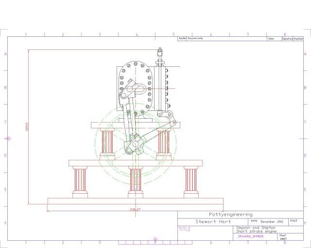
I've not bin Idle these last couple of weeks I've bin doing a bit of research on an engine that caught my eye. Its a bit of a strange beast it has a rotary action that I can best describe as a captive eccentric. The original was first displayed at the great exhibition and was shown powering some textile machinery, as far as I can find out only two were made, though there is very little documentary evidence for the second.

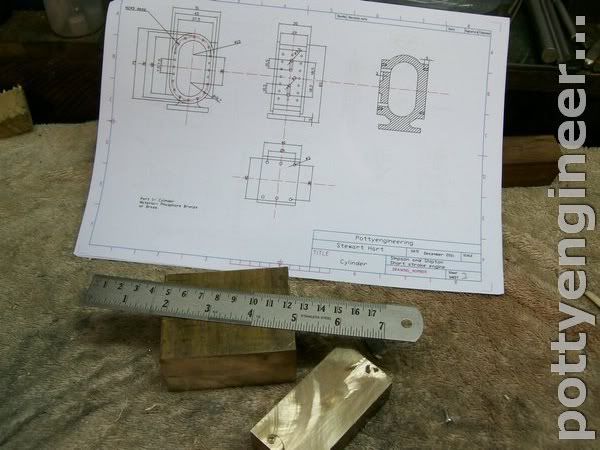
I've got enough of the drawing done to show you an assembly, but I still need to do more detailing of the parts, but its enough to give you an idea of how it will look.

Sht1-Model.jpg


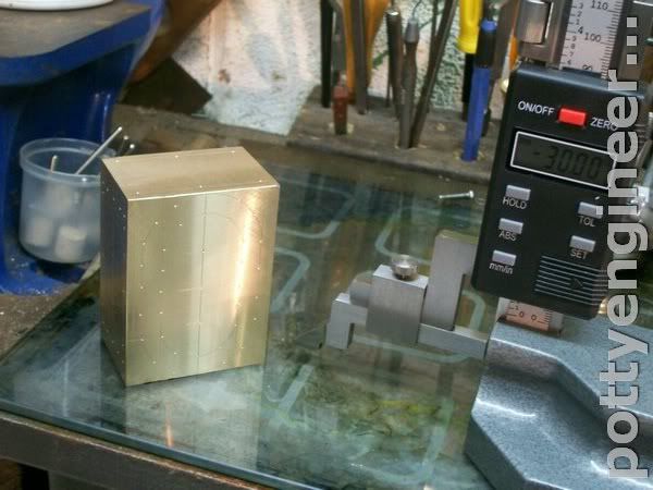
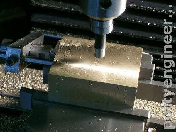
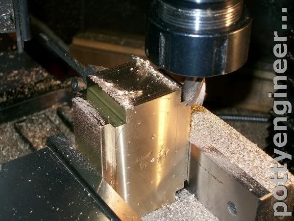
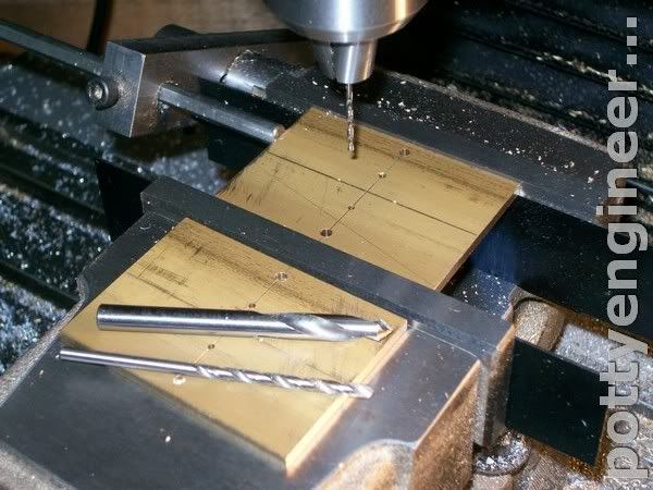
I'll slowly work on the drawing and start to get material together ready to make a start and cut metal in the new year.

Stew
 
Looking good so far Stew, to you have Anthony mounts articles on teh one he did?

Pat over on Classic steam is doing something similar with a Dake engine

J
 
Hi Jason

The club have copies of engineering in miniture with Antony Mounts article, I had a quick look at it to try and understand the valve arrangement, still couldn't get my head round it, I'm doing mine with a piston valve arrangement, I didn't read the full article, as I didn't want to be influenced to much by it, not that there is anything wrong with it, far from it, its a very nice engine.

I'll be using bar stock as far as posible and it will be about 4/5 the size of Antony's

I'll have a Look at Pats Build thanks for the information

Stew

 
Hi Jason

Just done some research on the Dake engine and i must say what a wonderful engine it is, worth doing a google on william dake, 3 or 4 page in there's a link to high pressure steam engines, that has some great animation of the engine.

Thanks for bringing it up

Stew
 
Started to cut metal on this engine, first job cut the cylinder out of a chunk of brass and square it up

131_1109.jpg


Next using my new digital height gauge from Santa mark it out and light centre pop the lines.

131_1111.jpg


Then in the mill with a wobbler find the edge of the lump and bring the mill onto its centre, and set the vice stop.

131_1117.jpg


Then working to the marked lines chew out the edge to start forming what will be the port face flip it over and do the same on the other edge.

Turn it on its end a chew out the end edge, flip it over and do the other end

131_1124.jpg


Sit it level on parallels check that we are still on centre, and drill a couple of 13mm on holes on the what will be the centre for the cylinder.

131_1126.jpg


I was getting a bit cold at this point so went in for a warm, I'll pick it up again tomorrow.


Any one who would like a copy of the drawing just send me a PM with your email adress on.

Stew
 
Ok Guys big red face time I dropped a bollock with the drawing

:'( :'( :'( :'( :'( :'(

I've made the cylinder too long, it should be the 30 + 15 + 1.5 = 46.5

I drew it as 30 + 30 = 60 it was only after I had drilled it that I started to think that looks too long better check it out,

Just measured things up and all is not lost I can still fit the correct length of cylinder in, but I need to chase the change through the drawings as it will impact on the con rods, cylinder covers and the valve chest.

So it's back to the drawing board.

Stew
 
Like your flash new height gauge Stew, nice present, much better than a tie or socks.
Sorry to hear about the wayward gonad, just goes to show, that it happens even to the best of us.
I am really looking forward to this one when you are back on track.

Les
 
Cheers Les

Things have bin a bit slow on this over the last week, what with having to redraw some of the parts, and other things getting in the way:- plus I went down with the dreaded puckes.

All fit now and bits redrawn.

First job was to put the bollock right.

So plugged the holes and respotted in the correct position.

131_1128.jpg


In order to get things in the correct position I had to use a boring head, just opened the holes up just enough to give a good register for a mandrel.

131_1133.jpg


Then turn a mandrell up a nice fit in the hole.

131_1135.jpg


Then transfer chuck and mandrel over to the RT and bolt the cylinder to it.

131_1144.jpg


Then machine the rads around the rim

131_1137.jpg


Turn the RT onto the horizontal and machine the pocket around the top.
First with a radius cutter

131_1146.jpg


Then take the meat away

131_1150.jpg


Then do the same with the base but leaving a flat for the foot to solder too.

131_1152.jpg


Your probably a bit baffled as to where I'm going with this, well I'm baffled as well :lol:

Stew
 
Got a little done today: made the cylinder base this will be silver soldered to the cylinder.

Started life as a bit of 12mm thick brass sqaured up and milled to size.

Then first with a end mill and finishing off with a 10mm bull nosed cutter machined out a plinth in its middle.

131_1154.jpg


It fits on the flat like this

131_1157.jpg


I'm not going to solder it just yet the cylinder covers will need soldering as well so I'll do them together.

Stew
 
Thanks for you interest Guys

Any way got the base soldered to the cylinder, it took two goe's my first atempt the nozzle was a bit small and I wasn't getting enough heat into it, swapped to a bigger nozzle and it went like a dream, at the first attemp I tought should I swap to a bigger nozzle, but I was to lazey and went with what was fitted, came out ok in the end its slightly skiwiff, but a light skim of the base should sort that.

131_1175.jpg


Next up the covers, I'm making these out of 1/8" thick brass, first job cut then off the bar and square the ends, then carfuly drill the centre holes 3mm to take dowels and a couple of 1/16 for brass pegs to locate a thickening peice.

131_1167.jpg


Then cut out the thickening peice square them up and drill them for the 1/16 pegs

131_1162.jpg


File a rad on each end

131_1165.jpg


And this is how they fit on the cover for silver soldering

131_1168.jpg


Job done:- the pic doesn't do it justice its a very neat joint.

131_1172.jpg


The covers have a curved slot that the piston rod runs in this has to be on a 75mm rad, and the covers have to fix centraly on the cylinder bore. so I made a fixture to hold the covers on.

A 10mm hole was drilled and reamed in the jig 75mm from this two 3mm holes were drilled to take 3mm dowel pins, and a hole drilled and tapped to take a clamp. I also made a 10mm clamp bolt with a 10mm register dia a neat fit in the 10mm hole in the fixture, this bolt screwed into the surface plate that I made some time ago to increase the capacity of my RT.

131_1160.jpg


and how it all fixes together.

131_1173.jpg


Stew
 
I'm still baffled. Perplexed even.
 
Hi Woodguy

This animation and explination you will find her Doug.
may help.

Thanks
Stew
 
Wow what an interesting engine
This will defiantly be on my watch list
Pete
 
Wow ... Santa was nice. You are going to really going to enjoy working with your new
digital height gauge. :)


Your project is going to be another learning experiencing for me,
will be following closely. ;)


Pat H.
 
Thanks for your interest Guys

Things should start to make sence from now.

I can now start treating the cylinder like a casting, the trouble with this design of engine is that its so weird, its difficult getting your head round feature that are important.

I figured that it will be important getting the slot that the piston rod moves in central with the cylinder hence the fixture I've made.

So to mill the slot first centre the RT on the mill spindle zero things up then, using the bolt secure the fixture to the table, but first clock it up level with the Rt set on zero deg.

131_1186.jpg


Then index 75mm bolt the cover to the fixture and with a 8mm slot drill mill the slot.

131_1190.jpg


Next drill the 2mm holes on the PCD, both ends

131_1195.jpg


Onto the cylinder centre it up on the mill zero the dials. and using a boring head bore out the cylinder vertically down, advancing 1mm vertical down again advance 1mm etc etc until its long enough.

131_1198.jpg


Did this for a couple of rouging cuts, then to finish advanced it 0.5mm/cut , this left a slight ripel in the bore but that will soon clean out with a bit of fine emery cloth wrapped around something flat.

Then on the centre line drill a couple of holes each side to take 3mm dowels.

131_1201.jpg


Locate the covers on the dowels and spot through 2mm followed through with M2 tapping drill.

131_1204.jpg


Centre the jig back up on the RT and radius the end of the covers.

131_1213.jpg


And this is what the covers look like on the cylinder, only got one finished before domestic duties called, I'll finish the other off tomorrow.

131_1221.jpg


Hope things are starting to look a bit clearer.

Stew

PS for some reason the Preview button doesn't seem to work ????
 
Interesting engine and really great construction techniques and photos. I will be following along with mouth open at the way you achieve things. :bow:
Thank you

Jim
 
Thanks Jim

Her's a pic of the covers the right way round, I think it looks happier the other way :D

131_1223.jpg


With both covers fitted i put a length of 8mm silver steel through the slot and measured the height side to side and front to back, and it was within 0.06mm:- not alf chuffed with that :D :D :D :D :D :ddb: :ddb: :ddb: :ddb: :ddb:

131_1222.jpg


Back on the mill and drilled and milled the air ways, and drilled m2 tapping for the valve chest.

131_1226.jpg


Then tapped the holes M2 using the tapping stand to get them square, these holes are on both side of the cylinder, on the model they don't do anything, but on the origonal the cylinder sides were spring loaded to take up wear hance covers both side.

131_1230.jpg


On with the valve chest now, first square it up to size, then centre spot where the bore is to go for the spool valve.

131_1233.jpg


Then in the four jaw chuck clock up a wobble bar centred on the spot centre.

131_1234.jpg


Centre drill then drill and ream 8mm.

131_1236.jpg


Swap it round clock the centre spot up on the face.

131_1238.jpg


Drill through into the 8mm bore and face the boss for the air coupling.

131_1242.jpg


Over onto the mill using centre the work and with the DRO drill the holes on the PCD for the coupling.

131_1246.jpg


Flip it on the back find the centre and drill the feed ports and 2mm for the studds

131_1248.jpg


That was a good morning work :D :D :D :D

Any one know where I can buy some M2 studding in the UK.

Stew
 
Thanks John

I'll give you a call

Stew
 

Latest posts

Back
Top