Upshur's opposed twin engine

Home Model Engine Machinist Forum

Help Support Home Model Engine Machinist Forum:

This site may earn a commission from merchant affiliate links, including eBay, Amazon, and others.
Thanks for the CAD demonstration Jason. Really comprehensive.
It's the sort of thing I used at work, but cut sections where I wanted them and moved parts to geometrically define the actual depth of foul, etc. rather than just pretty motion pictures. But I'm sure you do that as well, so you get dimensions for the clearance machining required. After all we are just talking of a simple right-angled triangle, so dimensions and angles are easy to calculate.
I just enjoy doing it in a few minutes on a sheet of paper, as it is simple and doesn't need a CAD system. (IMHO).
BEFORE CAD - I engineered a crankcase, cranks, rods and linkages to increase the stroke of a device from 7 1/2inches to 9inches using pencil and paper, including designing the con-rod swing and clearances to the adjacent cylinder ends. And reconfigured it to have a varying mechanical advantage from start to end of stroke. (From something like 2:1 at the start to 1:2 at the end of stroke. The input piston accelerated at about 105g! - calculated and measured peak - so we had to determine flexure and deformations of components as the forces and speeds were so high.).
That was a nice bit of drawing (Fun?) - to demonstrate to the Chief & Senior Engineers before my designs were bought-off. Maybe I should have used CAD but it hadn't been invented.... (Apple's first PC was launched about then..).
I'm sure all the contributors discussing this are equally capable of designing this. It just seems the designer missed it on the drawings that Brian is using.
And please remember this is OUR HOBBY. So please try and remain calm and enjoy what others present. (Even if I spout a lot of rubbish!).
K2.
 
Chill dude!!
No one was telling you how to "design or build model engines".
Sparky and I were merely pointing out that if you use SW to model the engine, you can run it through it's motions to highlight any possible interferences.
On the possibility that you were not familiar with how to do that, Sparky brought up a perfectly viable suggestion on where to obtain that information.
When you are constantly making on the fly adjustments and changes, It's not a big leap to think that maybe you are not aware of the power and features of the tool you use???

At least we didn't get a "bite me".

Fumble on......
Sid I listen to you on another forum. As long as it's about you, you seem to be a nice guy. But you seem to be a ankle biter, always looking to jab someone. So sad! Guess I'll be leaving TWO forums because of the likes of you, and others.
olf20 / Bob
 
Sid I listen to you on another forum. As long as it's about you, you seem to be a nice guy. But you seem to be a ankle biter, always looking to jab someone. So sad! Guess I'll be leaving TWO forums because of the likes of you, and others.
olf20 / Bob
Bob- I'm not sure what your reading, where, but you don't know what your talking about. (and I don't really care about your opinion).
I've posted my work mainly on HSM and some here. It speaks for itself, so....
I've offered advice that was pertinent to the subject, based on a subject that I have experience with. (CAD for example)
I don't comment on things that I don't have first hand experience with.

And BTW, I have complemented others' good work when it is displayed.

See ya!!
 
Last edited:
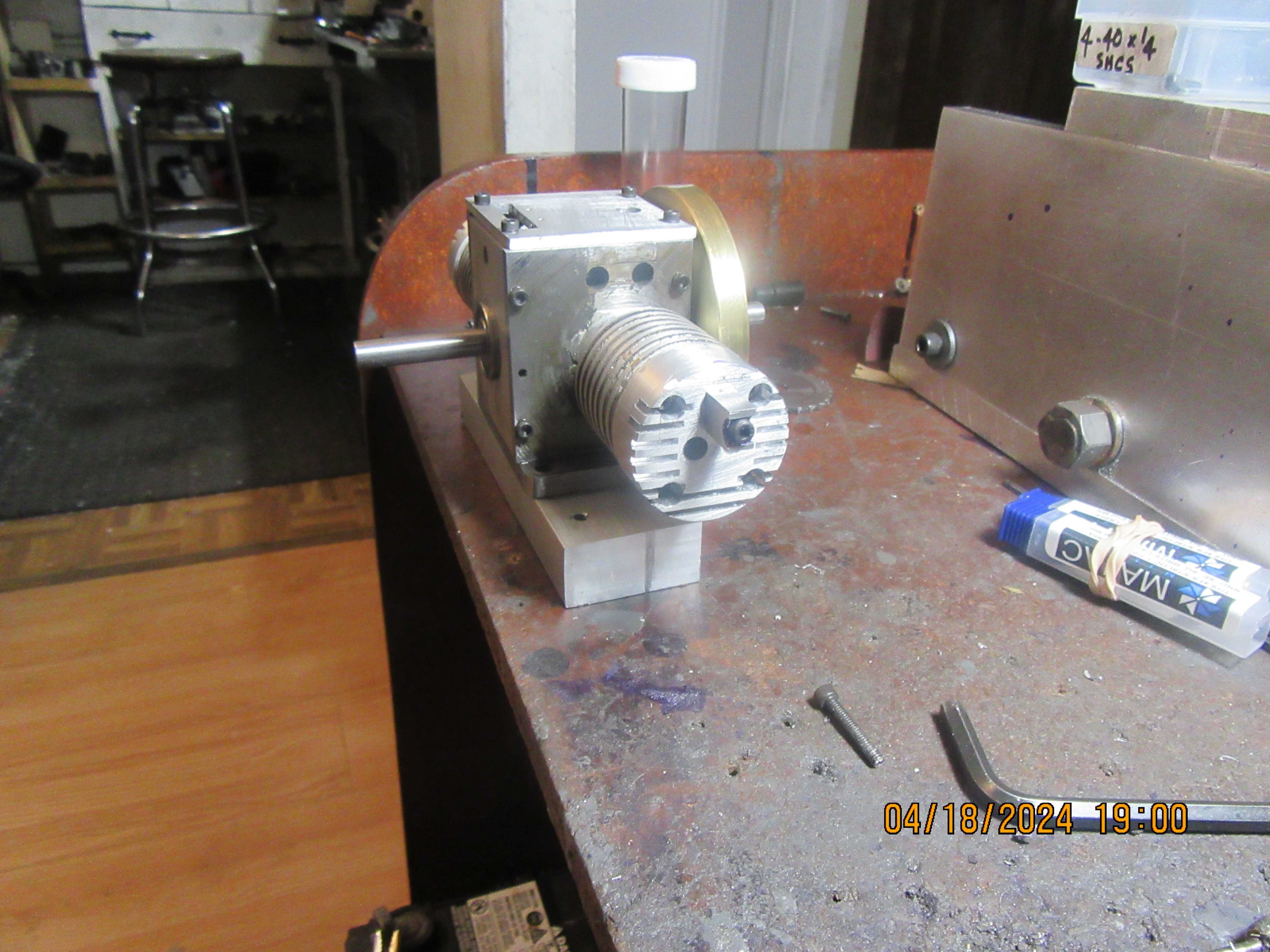
Today I cut cylinder head fins and made up a couple of rocker arm support towers. Not terribly exciting, but it took up most of my day. There is something a little fishy about the rocker support tower in the drawing package from Upshur. Haven't quite figured out what it is yet, but there is something about the #5-40 threaded holes tapped in the rocker arm support towers and in the head.
STIQrn.jpg
 
Last edited:
I see two little fishies

1. The thread into the head is quite shallow so you need to make sure you avoid the spark plug thread and also don't overtighten things and strip the shallow thread.

2. If the rocker post is also threaded as shown you may find it hard to get things to line up

You have also made me notice something else on the MEB drawings. The spark plug hole is shown with quite a close fitting 1/4" deep counterbore which could make it quite difficult to get at the hex of the sparkplug to do it up. Do the original Hamilton drawings have the same detail?

https://sparkplugs.morrisonandmarvin.com/

DSC04743.JPG
 
I don't have the drawings... but this looks to me like a half-moon machined into the post, for a shaft to fit into, that had a hole drilled through for the mounting bolt to retain. The rockers then hand on either end of the shaft.
1713507783659.png

I occurred to me that the pillar will see a load on one side, when the can pushes 1 valve, then a load on the other side - when the other cam pushes the other valve. So it sees an oscillating bending action from the rocker shaft and could be prone to fatigue?
But now I am curious to hear Brian's ideas about his "fishies"?
K2 :)
 
I see two little fishies

1. The thread into the head is quite shallow so you need to make sure you avoid the spark plug thread and also don't overtighten things and strip the shallow thread.

2. If the rocker post is also threaded as shown you may find it hard to get things to line up

You have also made me notice something else on the MEB drawings. The spark plug hole is shown with quite a close fitting 1/4" deep counterbore which could make it quite difficult to get at the hex of the sparkplug to do it up. Do the original Hamilton drawings have the same detail?

https://sparkplugs.morrisonandmarvin.com/

View attachment 155435
Interesting Jason! I've not started on my heads yet. I think I will try taking a few thou at a time off the bottom of the rocker posts to try to get a tight lined up fit. I'm going to use rimfire vr2 (maybe long reach) plugs but will try to get hold of a thin sided box spanner to work out how much material to take off.
Cheers
Andrew
 
Another option may just be to drill the post with a clearance hole

Or do as you say adjusting the end until things line up. But I would use a short length (about 5/16") of threaded rod which can be loctited into the head and not taken out again that the post can be screwed onto. You can then use the remaining female thread in the post to take a screw to retain the cap and shaft.

The long reach plug should may* be OK, the counter bore would only need to be about 0.0150" deep to put the end of the plug in the right position which will mean the hex section will protrude outside of the head.

*The only thing to watch if you do that is that the pushrods don't foul the plug. If that is the case then a standard length plug with the 1/4" deep counterbore which can either be made a larger dia or you could mill a flat on the edge of the head so the hex is exposed.
 
Andrew, I think there may be a note on the original Upshur drawings to do what I suggested. EG a stud that stays loctited into the head that the post screws onto and a shorter screw to hold the pivot and cap to the post not as it is shown on the MEB drawings with a screw through the lot. Just waiting for confirmation. Though Brian should have that note if it is on the originals.
 
Andrew, I think there may be a note on the original Upshur drawings to do what I suggested. EG a stud that stays loctited into the head that the post screws onto and a shorter screw to hold the pivot and cap to the post not as it is shown on the MEB drawings with a screw through the lot. Just waiting for confirmation. Though Brian should have that note if it is on the originals.
To gain a little more engagement for the rocker post (and I like the stud idea), can the spark plug be moved down?
Maybe .050" I doubt it would make any difference to the performance, but would help the rocker post situation.

Sid
 
Brian, i realize you are building a different engine, but on the single the rod are turned lengthwise so to speak, or rounded over edges. i only say this is thinking maybe he redisgned the blue prints later on and my copy has the redesign? cylinder size and such on yours appear to be the same as the single so wondering if maybe this picture below might be a redesign so it clears?

edit - also want to say it doesnt matter because you solved your problem by chamfering the bottom of the cylinder so guess this is a moot or muut point (however you speel that.
1713531742985.png
 
Sid that would probably be an option just have to make sure the counter bore did not break out the lower face particularly if it needs to be enlarged to get a wrench to fit.

Maybe angle the hole a bit too
 
Sid that would probably be an option just have to make sure the counter bore did not break out the lower face particularly if it needs to be enlarged to get a wrench to fit.

Maybe angle the hole a bit too
Both yours and Sids comments on the spark plug hole are excellent BUT did Brian already machine the spark plug hole? If he did, I highly doubt he would remake the heads. The rocker post is another matter.
 
Both yours and Sids comments on the spark plug hole are excellent BUT did Brian already machine the spark plug hole? If he did, I highly doubt he would remake the heads. The rocker post is another matter.
I didn't see the spark plug hole per the last picture.

Sid
 
I didn't see the spark plug hole per the last picture.

Sid
Isn't it located on the side of the head on those engines? I also looked but didn't see any plug holes, certainly not in the customary spot on the top of the head. Holes in the side wouldn't show in the posted pics I don't think. Then again, Brian may not have made those holes yet.

To confuse things further, there seems to be two versions of the twins plans, plus the near identical single cylinder version THEN it is unknown if Brian made any tweaks. That gives 4 possibilities to help further confuse things.

On the rocker arm post, I see the concerns. If I was doing it from scratch, now knowing those concerns, I would probably make the raised rocker arm boss one piece as part of the head. Does not apply here of course.
 
Last edited:
The single uses a different arrangement to hold the post as the plug is on the opposite side of the head to where the rocker post and push rods are.

The twin has them both on the same side so that the plugs are high up and less likely to be a problem if the engine floods.

The single also has a much shallower counterbore that is not much more than a spot face so easy to get a wrench in place. But that is possible as there is no risk of pushrods getting close to the plug.
 

Attachments

  • single.JPG
    single.JPG
    27.7 KB · Views: 0
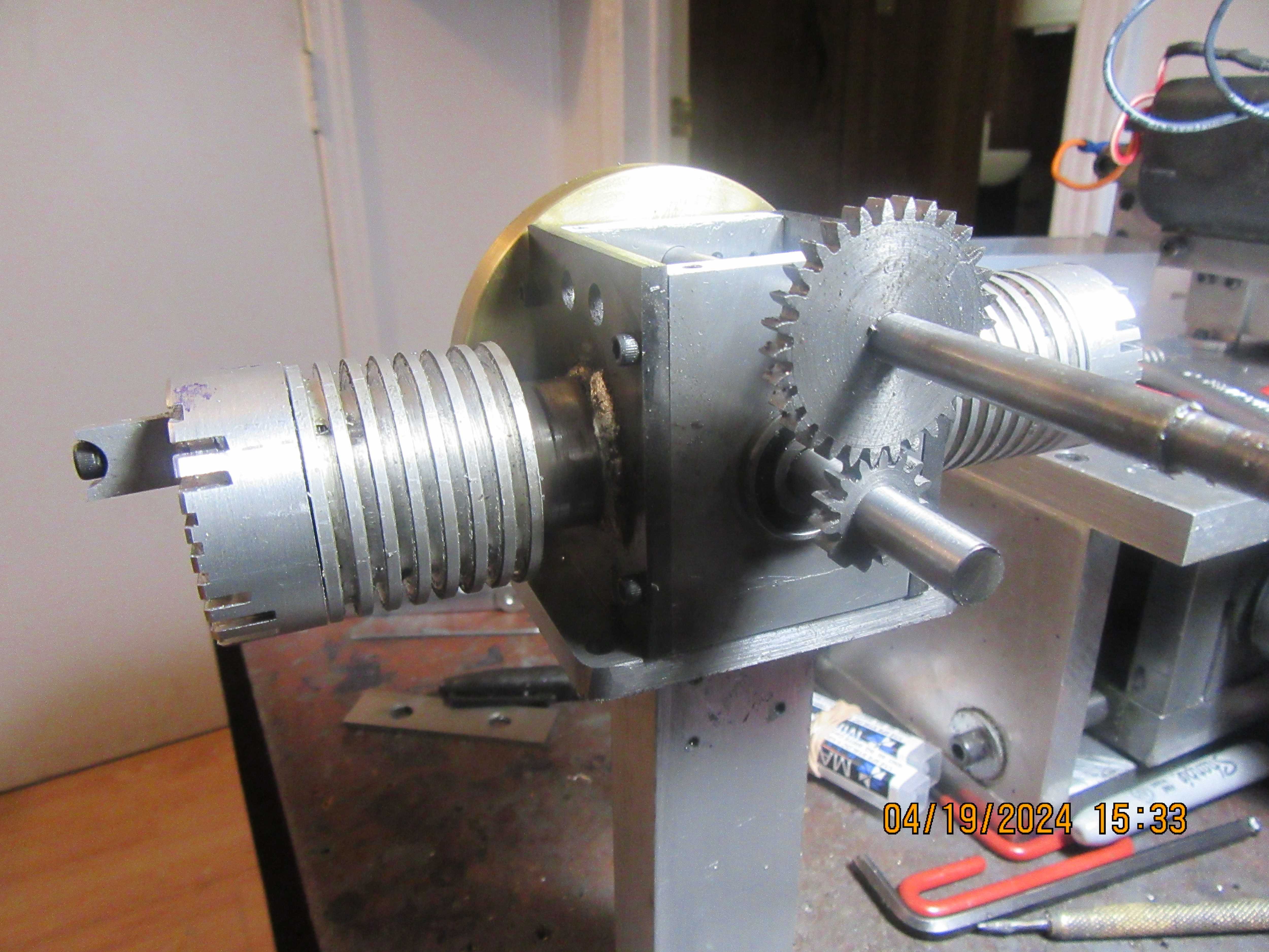
Today I broke out my gear cutting stuff, and made gears for the Upshur. These gears actually fit inside the crankcase, but I stuck them on the outside just to be sure that they meshed properly and to take the picture. I haven't had lunch yet and it's 3:52 here, so I'm up up and away to eat something!!!
ztkEmS.jpg
 
Back
Top