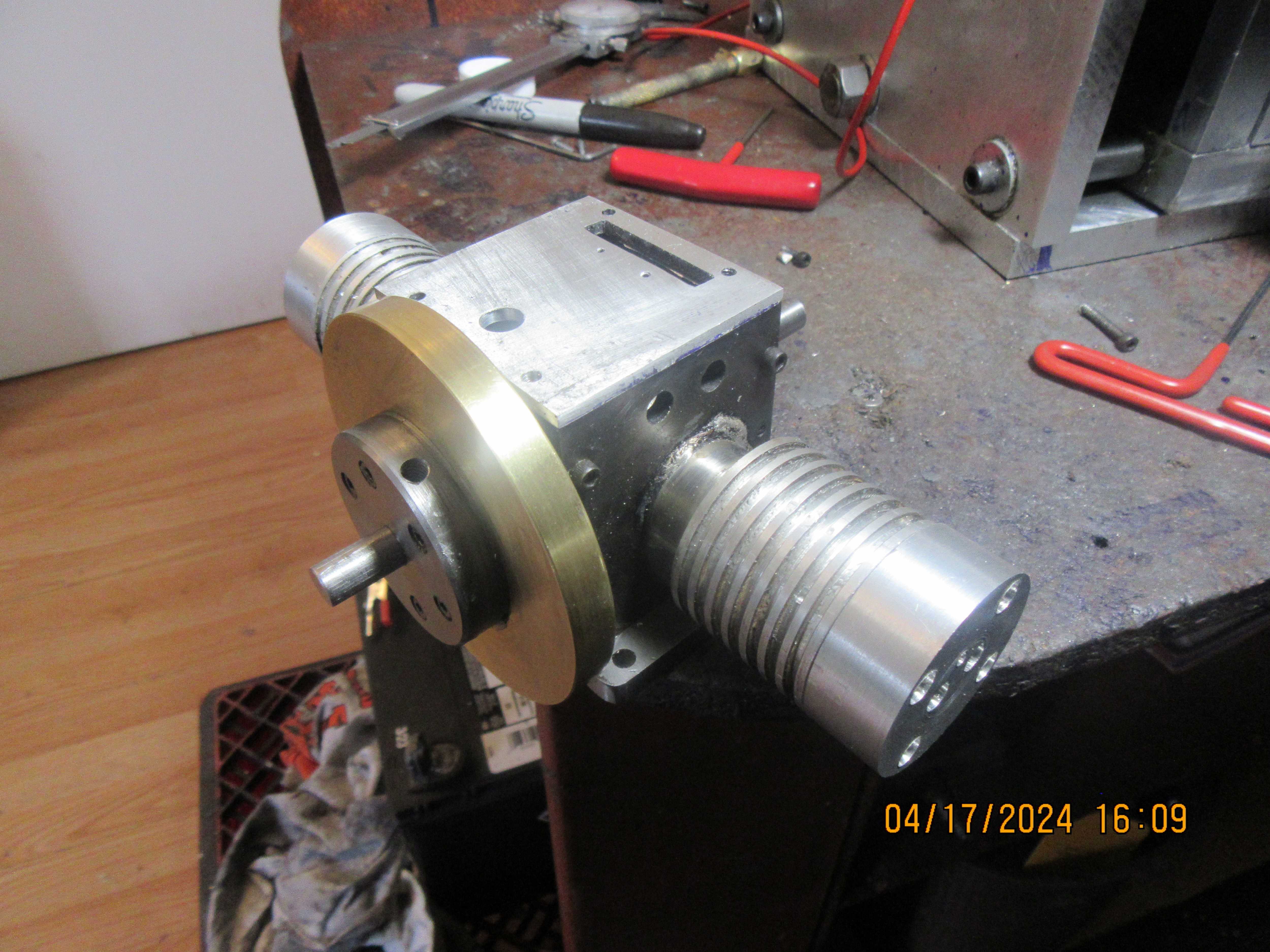
So, today I reached a milestone with the Upshur opposed twin cylinder engine. I have assembled all of the major components and everything goes round and round and up and down like it is supposed to. This engine is very small, having a 3/4" cylinder bore, and it will be my first engine with a distributor. The sides of the connecting rod do interfere with the bottom of the cylinders, preventing a full 360 degrees of rotation. This was solved by putting a large 30 degree chamfer on the bottom of the cylinders. Tomorrow I will probably make the cylinder heads.

You are using an out of date browser. It may not display this or other websites correctly.
You should upgrade or use an alternative browser.
You should upgrade or use an alternative browser.
Upshur's opposed twin engine
- Thread starter Brian Rupnow
- Start date


Help Support Home Model Engine Machinist Forum:
This site may earn a commission from merchant affiliate
links, including eBay, Amazon, and others.
- Joined
- Sep 2, 2011
- Messages
- 1,342
- Reaction score
- 360
Hi Brian, im referring to the upshur vertical single i built close in design to the one you are doing. less complex given its a single but bearings and plates and cylinder were done the same way you are doing on yours except just a single.I have used sealed ball bearings. Werowance--was it this engine that you built? If so, please give me a link.---Brian
heres my build. which you and many others gave me lots of good advice and help on to get me thru it.
https://www.homemodelenginemachinist.com/threads/werowance-attempts-upshur-vertical-single.31677/
Looking good! Is the potential rod to cylinder foul due to the rods being off-set for the centre line of the cylinders? I am surprised you have had this foul. Easy to spot when checking on the drawing board, when working on the general arrangement. And the angle where the rod is at max "throw" is given by simple geometry - rod centre length / crank radius = tangent of max throw angle. Just takes a few construction lines. Maybe CAD doesn't enable an easy projection to check crank throw? I don't have CAD so have to "work it out by brain power"... (A lost art?). I would have thought the original designer would have sorted it out....?
K2
K2
Brian's rods don't look quite the same as the original designer drew them so it was probably OK on the original.
Rods should not be offset from ctr line of their respective cylinder
Cad makes it very easy to check as you can rotate the virtual crankshaft and see how all the parts move
Rods should not be offset from ctr line of their respective cylinder
Cad makes it very easy to check as you can rotate the virtual crankshaft and see how all the parts move
Last edited:
My con rods are centered on the cylinders. It's not the flat sides of the rod that fouled, it was the edges of the rods that fouled the bottom of the cylinders. I was kind of expecting this to happen, as Andrew Whale from the U.K. had the same problem with the same engine. Andrew solved it by whittling some more off the rods. I solved it by putting a chamfer on the bottom of the cylinders. The rods are made to the original drawings.
Last edited:
Today I didn't accomplish much. I made both cylinder heads, but I had to go across town and buy a slitting saw to cut the fins into the heads. I did have the correct slitting saw in my shop, but it had dulled from a lot of use, and it costs as much to have it resharpened as it does to buy a new one.
Properly modeled in a 3D cad world, it is easy to do interference checks. Key term, properly modeled.Looking good! Is the potential rod to cylinder foul due to the rods being off-set for the centre line of the cylinders? I am surprised you have had this foul. Easy to spot when checking on the drawing board, when working on the general arrangement. And the angle where the rod is at max "throw" is given by simple geometry - rod centre length / crank radius = tangent of max throw angle. Just takes a few construction lines. Maybe CAD doesn't enable an easy projection to check crank throw? I don't have CAD so have to "work it out by brain power"... (A lost art?). I would have thought the original designer would have sorted it out....?
K2
No reason in SW this can’t be done.
Yes, of course you are right. One of these days I will have to get someone to teach me how to use my Solidworks.
There are excellent tutorials on youtube teaching the advanced features of solidworks. I used it heavily in building a gatling gun I recently designed and built. Using the animation features I was able to "operate" everything on screen before cutting metal. It sure saved a ton of issues tha t would not have been noticed until the build was well underway. I learned those features and their use with the youtube tutorials. I also used the solid models to generate the cnc toolpaths to make the parts. (I realize you don't use cnc so that part does not apply)Yes, of course you are right. One of these days I will have to get someone to teach me how to use my Solidworks.
I agree, youtube has a lot of good tutorials.
I've found good information for doing animation in Creo.
Sometimes it may take a bit to find exactly what you need, but it's probably there.
I'll bet local colleges would offer classes too.
I've found good information for doing animation in Creo.
Sometimes it may take a bit to find exactly what you need, but it's probably there.
I'll bet local colleges would offer classes too.
Sid--You did me a big favor and made a pair of excellent cams for me. I appreciate it. I doubt that anyone is going to be able to show me anything about Solidworks. The solid models I made were made from a set of purchased plans from Hamilton Upshur's wife. The interferance between the connecting rod and the bottom end of the cylinder is not uncommon. I don't need you nor Sparky to advise me on how to design or build model engines. Leave it. I don't question your abilities nor your craftsmanship. I will go to the moderator of this forum and complain about you.---Brian Rupnow
Hi Brian, I apologise for starting that bit of the thread. (post #63).
Opened my mouth and put my big foot in it (Again!).
I was not criticising your ability, just the original designs should have done the job.
I was simply saying it is a "common problem" that in the heat of designing something, Designers miss things... that should be easy to do. (I do!).
I recognise you are following another's plans this time, not your own design and don't doubt your competence.
I am "CAD incapable" as I had to learn a new system every 2 or 3 years at work - and each one was seldom used in my varied job, so I ended-up only being frustrated by each new system having a whole load of new commends and processes to do the same job! "Practice-practice-practice" and you get good at these computer processes. But I just had to "do the odd job and move on" - so never managed to develop CAD skills.
But my draughting on paper still does everything I need. And I think working on paper helps me think of things, instead of being distracted by "How on earth do I do the next bit?"... - And draughting on paper takes me through the manufacturing processes as well...
I am sure when you design something on your CAD, the CAD is just another tool of which you are completely competent, as you produce excellent model designs from what I have seen.
Please forgive me if I started something that inspired the wrong comments from others. NOT my intent.
Keep on doing what you do as we need your lessons in patience, modelling, etc.
K2
Dear Mr.RupnowI don't need you nor Sparky to advise me on how to design or build model engines. Leave it. I don't question your abilities nor your craftsmanship. I will go to the moderator of this forum and complain about you.---Brian Rupnow
What's up with you? At first you are crying around cause you can't get your engine to run. You never take the advice you have been given from other builders. You ask for help but always do your own Thing. You tell us day by Day about simple things you get stuck with. A lot of People had a lot of patience with you. And Now this??? You want to complain about others here who were trying to help? This time you went too far. I'm out of your 'building stories'. You should take a long break from Posting in this forum. I'm really disappointed.
That may explain why I can see differences as I am looking at the plans that were in Model Engine Builder.The solid models I made were made from a set of purchased plans from Hamilton Upshur's wife.
I have marked the sizes they give for the big end which are clearly different to yours and they also have the screw holes in the middle not breaking out the side. With your conrod having the 0.250" length longer that would make the rod wider and more likely to foul.

What the hell is the matter with you guys? This is the reason why LOTS of great modelers machinists don't / won't post their stuff. If you don't like someone's designs / comments DON'T visit!!Dear Mr.Rupnow
What's up with you? At first you are crying around cause you can't get your engine to run. You never take the advice you have been given from other builders. You ask for help but always do your own Thing. You tell us day by Day about simple things you get stuck with. A lot of People had a lot of patience with you. And Now this??? You want to complain about others here who were trying to help? This time you went too far. I'm out of your 'building stories'. You should take a long break from Posting in this forum. I'm really disappointed.
GOOD GRIEF!
olf20 / Bob
It seems Andrew Whale wa susing teh MEB drawings so less likely to be a difference between the ones from Mrs Upshur and the ones from MEB so I drew a few parts to take a look. Steamchick this is what can be done with CAD.
I should say there are a couple of variables on the drawing as the width at the top and bottom of the conrod are given as approx 0.250" and approx 0.395". It also says a "small" chamfer to the bottom of the liner which could be open to interpretation. I drew the rods to the size given and added a 0.02" x 0.02" chamfer.
As the video shows there is a clash between liner and rod.
I played around with the width of the rod at the big end and would suggest that anyone wanting to build this engine in the future including Timo reduce the 0.395" to 0.344" which is a bit more than "approx" which will give safe clearance. if using the 0.156" side plate thickness.
Chill dude!!Sid--You did me a big favor and made a pair of excellent cams for me. I appreciate it. I doubt that anyone is going to be able to show me anything about Solidworks. The solid models I made were made from a set of purchased plans from Hamilton Upshur's wife. The interferance between the connecting rod and the bottom end of the cylinder is not uncommon. I don't need you nor Sparky to advise me on how to design or build model engines. Leave it. I don't question your abilities nor your craftsmanship. I will go to the moderator of this forum and complain about you.---Brian Rupnow
No one was telling you how to "design or build model engines".
Sparky and I were merely pointing out that if you use SW to model the engine, you can run it through it's motions to highlight any possible interferences.
On the possibility that you were not familiar with how to do that, Sparky brought up a perfectly viable suggestion on where to obtain that information.
When you are constantly making on the fly adjustments and changes, It's not a big leap to think that maybe you are not aware of the power and features of the tool you use???
At least we didn't get a "bite me".
Fumble on......
Last edited:
AndrewW
Well-Known Member
It seems Andrew Whale wa susing teh MEB drawings so less likely to be a difference between the ones from Mrs Upshur and the ones from MEB so I drew a few parts to take a look. Steamchick this is what can be done with CAD.
I should say there are a couple of variables on the drawing as the width at the top and bottom of the conrod are given as approx 0.250" and approx 0.395". It also says a "small" chamfer to the bottom of the liner which could be open to interpretation. I drew the rods to the size given and added a 0.02" x 0.02" chamfer.
As the video shows there is a clash between liner and rod.
I played around with the width of the rod at the big end and would suggest that anyone wanting to build this engine in the future including Timo reduce the 0.395" to 0.344" which is a bit more than "approx" which will give safe clearance. if using the 0.156" side plate thickness.
View attachment 155416
Very interesting Jason. To be honest I think I missed the reference to a "small" chamfer at the bottom of the liner.
Cheers
Andrew
Funny enough I drew an alternative liner a couple of days ago for Timo and put a 1mm x 1mm chamfer on that as it just looked right to me and is the sort of size I would have done if designing myself as it makes it easy to get the piston with it's rings into the bore. What do you know that just clears the conrod. So really comes down to what the individual builder calls "small"
Clashing conrods and truck guides or cross head guides are quite common, I'll often flick back and forth between the parts making adjustments if something touches. The joy of CAD is I can section the assembly and see clearances change as parts are altered directly in the assembly which is a lot easier than trying to do it once you have cut metal. That is why these days I will redraw anything I build from plans.
Clashing conrods and truck guides or cross head guides are quite common, I'll often flick back and forth between the parts making adjustments if something touches. The joy of CAD is I can section the assembly and see clearances change as parts are altered directly in the assembly which is a lot easier than trying to do it once you have cut metal. That is why these days I will redraw anything I build from plans.
When drawing an engine in Alibre, I quickly learned to make the parts move while in the CAD program and avoid collisions. The drawings reflect the designer's information, from their drawings, and printed and verbal text. As you can see from this drawing from Issue #7 of Model Engine Builder, a chamfer is noted at the bottom of the cylinder.
Best,
Mike
Best,
Mike
Attachments
Similar threads
- Replies
- 413
- Views
- 39K
- Replies
- 25
- Views
- 3K
- Replies
- 22
- Views
- 1K
- Replies
- 61
- Views
- 8K