TB2 - Modifications to the build

Home Model Engine Machinist Forum

Help Support Home Model Engine Machinist Forum:

This site may earn a commission from merchant affiliate links, including eBay, Amazon, and others.

Brass_Machine

Well-Known Member
Joined
Aug 28, 2007
Messages
1,314
Reaction score
7
Base - Will be made thicker and larger footprint to allow for use of cap head screws and some detail work.

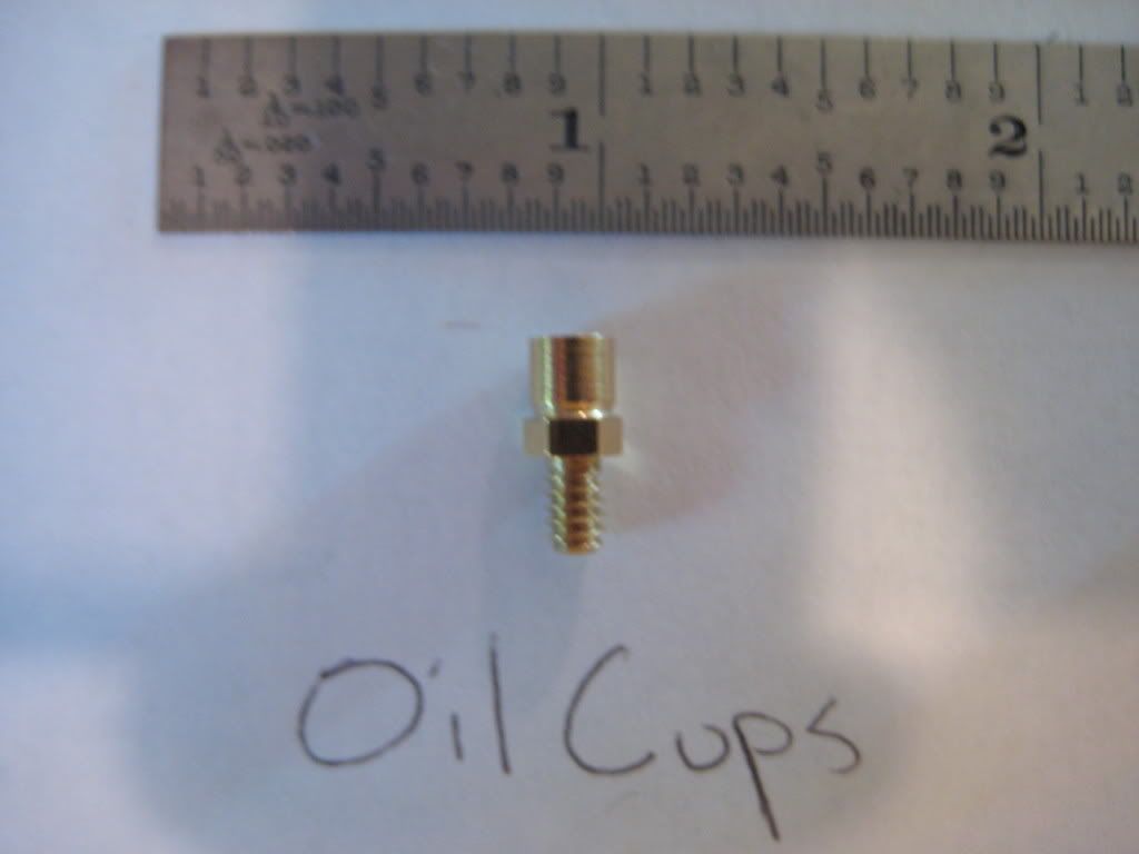
Bearings - a threaded 6-32 hole to allow the use of oil cups

Cylinder - 1/2 " longer shaft to allow mounting of the flywheel on the outside.

Extra spacer - Machined to the width of the flywheel to allow flywheel to be moved to the outside of small bearing.

Cam Ring - Machined to allow lettering at the top. Color still undecided

Forks - Wes's idea of a set screw


I would Like to offer to donate oil cups if anyone would like them Oil cups have 6-32 thread.

pic034.jpg


-Bret
 
I really like those oil cups. I wonder if we can work them in?
 
They could go on top of the bearings fine i think? I'll have to look at my print:eek:)
 
It would be nice for provisions to disassemble the rod forks and the piston from the piston rod. The way it is, they are soldered together at assembly :eek: There is no way to disassemble them. They could probably be drilled for a wire or maybe drilled and tapped to 0-80 or something? What does everyone think?

Wes
 
As for the forks, why not thread the ends of the rod and use two small jam nuts on each end to hold them in place? Adjustment would be easy and once in place the nuts could be secured with blue loctite.
 
Drill and pin won't work as it needs to be fitted at time of assembly to the cam ring for a spacing of .005. as for threading the fork that wouldnt work as you wouldnt be able to spin the fork to adjust it as the retaining ears would get in the way, threading the rod end could be done, although it would induce some wobble in the fork as you would not be able to stabilize the fork on the little stub of threaded rod. There isnt much room for a set of jam nuts either as the piston end moves pretty darn close to the fork at full travel. :-\

-Bret
 
What I had thought of doing on my existing engine was to change the fork to widen the slot for the rollers and insert a PTFE keyed washer on each side of the roller to act as flanges. Cut down the fork length so it is the same as the roller on the end nearest the cam. Then the pins could be removed and the washers and rollers removed to remove the cylinder assy from the cam ring. This still does not let you disassemble the piston from the cylinder.

Since this is a new build, it would be possible to change the internal dimensions on the cam ring to allow the piston rod to be lengthened by about 0.160 overall so the ends could be threaded and a THIN jam nut used against the ends of the fork. But to do the job right, one end of the rod should be right hand threads and the other left hand threads, and the forks and jam juts would also have to be left and right hand pairs. Otherwise you would be limited to adjustments of half the pitch of the thread. All the other parts, bearing blocks, base, etc could remain the same. I have not started the cam rings yet, so this change is still possible up until then. I think that making left handed nuts and threaded forks and piston rods is probably more work than it is worth.

I have attached a drawing of what I would do as far as modifying the fork and the guide washers. I have not tried this, but I think that it should work OK.


Drawing2.jpg
 
I was thinking that maybe we could turn the bottom of the fork (the part with the hole to be soldered on the shaft) thread it, slit it vertically with a really thin-kerf slitting saw, and then use a thin-profile nut on it as a compression type fitting? If we do enlarge the ID of the cam ring this would allow a little bit bigger nut as well. (We do have a whole 1/8th of an inch to play with, after all....)

Joe
 
I don't think it would be good threading the piston rod. The only adjustment you would have is a half turn at a time. Could the forks be made a touch thicker on one side and be drilled and tapped for a setscrew? This would let you adjust the legnth.

Wes
 
My suggestion on threading the rod did not include threading the fork. If the hole in the fork is equals the diameter of the rod, then there is unlimited adjust, not half a pitch.

I had another wacky idea in thinking about this, so here goes (ignore if ridiculous):

The fork has to be held in place for two reason: keep the wheel tracking the cam ring, and to maintain the correct length. If the wheel were to be notched to fit the ring, it would track itself and prevent the fork from rotating around the rod. Therefore the only adjustment to the fork is proper distance. So thread the end of the rod and use a jam nut to press the wheel against the cam.

To do this might require widening the fork and wheel to fit the cam, or rounding off the inside of the cam surface.


I like Wes's idea about a setscrew. There would only be a minor change to the fork and nothing else would change. Use a flat tip set screw so the shaft does not get a a dimple in it that the set screw would try to go into during adjustment.

Gail in NM,USA
 
There could also be a small flat on the piston rod to keep things from turning. I like the idea of the flat bottomed setscrews. If the piston is not removable, I don't see that as a problem. I mainly wanted to be able to take it apart for cleaning.

Wes
 
You know, not meaning to sound like a bunch of sour grapes, but as the person who brought this item up specifically as a reason to upsize the engine, this would have been all alot easier if we upsized the engine......... :big: :big: :big:

If you twist my arm ::) I can order a 3-C 5/16" square collet too.

I like the setscrew Idea too. I think starting with 5/16 Square stock instead of 1/4" square stock will give me plenty of meat for the setscrew hole. I may even plan to use a SS hex head bolt for the setscrew. Nice look.

The roller axles will need to be longer though..
 
I shipped the brass pieces to Kirk and Eric last Wednesday..... I don't have any larger dia. in that amount.They could be dedicated flywheel builders and use it for a future build. ;D
Being my first one..... are we waiting for a close to critical dimensions mods before we start machining? I don't want to make wrong size parts. ;)
Dick
 
Given that Gail's engine runs with no flywheel, the flywheel dimensions see pretty non-critical. Even if the engine is scaled up some we could keep the flywheel dimensions the same, or just thicker.
 
Not much thicker Kirk, I cut to length to be sure I had enough to get all the pieces. There is an extra .100" for facing and squaring. ;D
I was thinking of proportional appearance really not functional. Good point that it really isn't even needed.
Dick
 

Latest posts

Back
Top