Built up Flywheel-2011

Home Model Engine Machinist Forum

Help Support Home Model Engine Machinist Forum:

This site may earn a commission from merchant affiliate links, including eBay, Amazon, and others.

Brian Rupnow

Design Engineer
Project of the Month Winner
Joined
May 23, 2008
Messages
14,996
Reaction score
8,293
Location
Barrie, Ontario, Canada
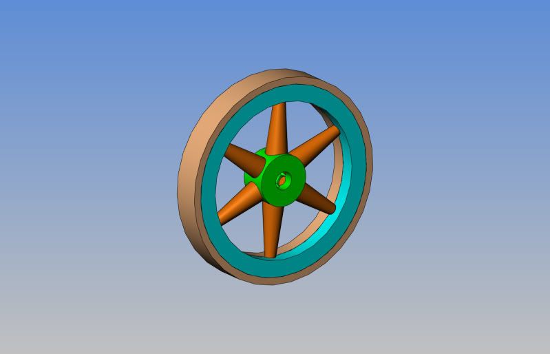
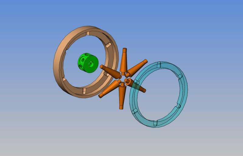
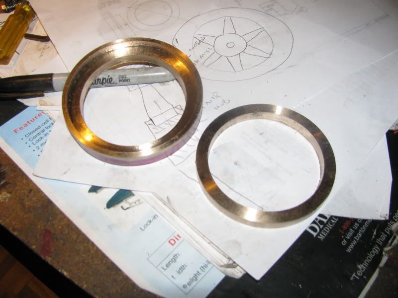
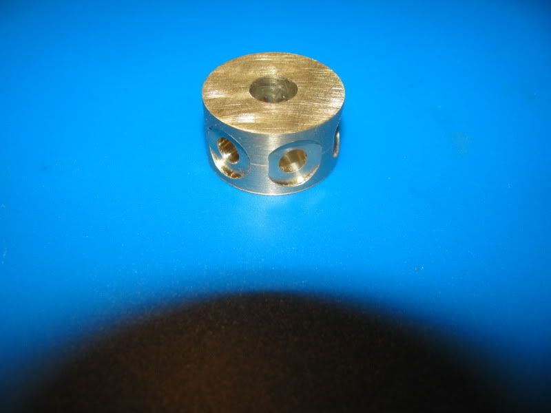
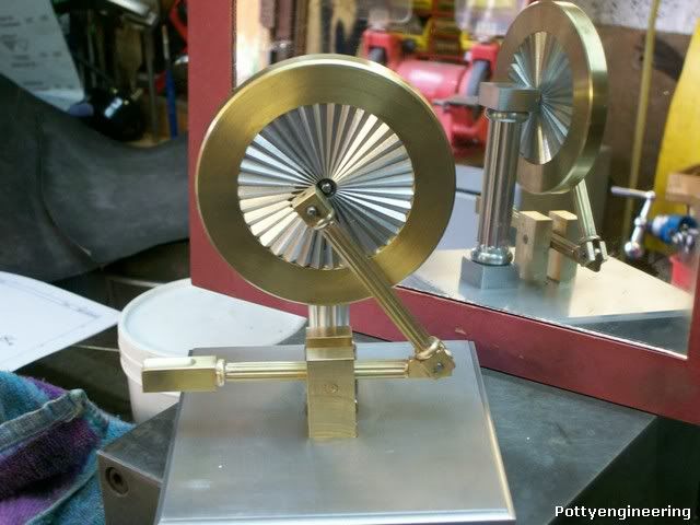
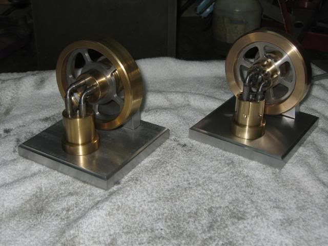
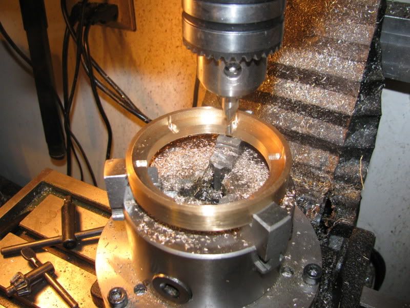
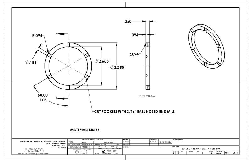
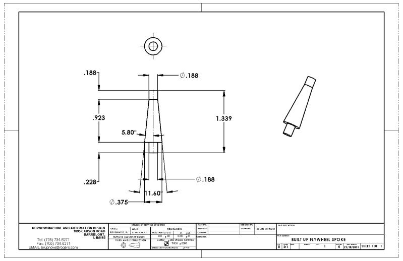
I need to make a flywheel for my Popcorn engine, and although I probably could make one with "wiggly" spokes, I have decided on a somewhat different approach. I have designed a "built up" flywheel in which one could use just about any kind of spokes they could dream up, and requires no soldering nor fasteners. I'm not 100% sure this will turn out okay, but we will go along for the ride and find out!!! The two models posted here show it "together" and "exploded" to give some idea of the construction method. The spokes are assembled to the hub with Loctite, the hub and spokes are then layed in the milled pockets in the outer rim, then the inner rim is Loctited into the outer rim, capturing the spokes in place. This means that the spokes can be an entirely different metal than either the hub or outer rim.
BUILTUPFLYWHEELASSEMBLY.jpg

BUILTUPFLYWHEELASSEMBLY-EXPLODED.jpg
 
Here is the outer rim, made from the remains of that 3 1/2" o.d. x 2 1/2" i.d. x 9" long chunk of bronze tube that I bought last year. I find machining this stuff absolutely terrifying---The tools have a tendency to grab and dig in, I am constantly bombarded by hot powdered bronze while machining it, and I'm scared right to death that the tool will dig in, rip the peice out of the chuck, and send it caroming around my tiny shop like a mad Kamikaze. You can see the counterbored area where the spoke pockets will be machined, and the inner rim fits into.
POPCORNMOVIE001.jpg
 
Here you can see the inner and outer rim, finished except for the spoke pockets which will be put in with a ball nosed end mill. this time I got lucky with my turning and boring, and it actually is a very good sliding fit when the two peices are put together.
POPCORNMOVIE004.jpg
 
This is the finished hub. The slight counterbore is to let the base of the spoke snuggle down into the curved outer surface when assembled.
POPCORNMOVIE005.jpg
 
Great plan Brian! and nice looking parts. The popcorn will look great with that baby on there.

I know what you mean about the bronze, it's like riding on a motorcycle in a sand storm.

Kel
 
Brian, it is far too late at this point in time to turn back and your work has all been exemplary, however, in my worthless opinion, anything other than a curved spoked flywheel on a popcorn engine is merely another mill type. The curved spokes are one of the first things that catches the eyes of the admirers and the imagination of the younger at heart. I for one do so hope that you will indeed make the curved spoke item and provide the engine its just deserved character. :bow:

BC1
Jim
 
Brian will you be assembling the flywheel in a jig to keep it concentric or putting it back in the lathe and boring it true to the outer rim once its dried?

Like Jim if a popcorn does not have a double curved flywheel it is really just a open trunk guided horz engine, would be nice to see it with the curves.

J
 
How are you going to put the pockets in the rim for the spokes Brian ???

Only way I can see is to use a ball nosed slot drill.

I've built four fly wheels know with loctite, none of them have failed, I don't think the retaining ring is needed.

I think its all to easy to over estimate the load on the flywheels of models, and underestimate the strength of adhesive.

In my other life I was involved in the design of products that were held together with adhesives, the key factors being the contact area of the bond, and the aplication of the adhesive onto clean mating surfaces, in this case freshly machines parts cut without oil will be ideal, and only the smallest amount of adhesive is required anything outside the contact areas is just waste.

Hope this helps

Stew

 
Thanks for this post - been thinking of a built up flywheel for my next project - so I'll be following with interest.

Ken
 
To Stew's point, NASCAR " Cup" cars have 800 HP and have drive shafts that are held together with Loctite products......I have a 6 HP frameless motor on a product I designed that has it's rotor held on with Loctite retaining compound....several in the field in the far east running 24/7. I sleep just fine at night.

The stuff's good!

Dave
 
Her's an example of my flywheels

100_3555.jpg


IMG_2040.jpg


100_5002.jpg


131_0758.jpg


And her's a picture of a little experiment I did this morning a 2 lb chunk of brass being held up by a 10mm dia brass bar stuck to it with loctite 603.

131_0856.jpg


You can get all theoretical with this and work out the loading etc, loctite publish performance details of their products, and it would be quite an easy calculation for those so minded to do, but this shows just what sort of performance you can get from the stuff.

Sorry about the ugly mug in the last pic

Stew
 
And everything positioned together except for the spokes. Yes, I will be making a simple "alignment fixture" when putting everything together to maintain concentricity, and it will get a "clean-up" pass on the lathe when all the Loctite has dried.
POPCORNMOVIE010.jpg
 
Well Dang!!! I'm liking this!!! I decided to use brass spokes instead of aluminum because when I looked in my stockpile, I didn't have any aluminum the right size. this weekend I will build a simple fixture to hold everything true and concentric and Loctite everything.
FLYWHEELFIRSTASSEMBLY001.jpg
 

Latest posts

Back
Top