Pat
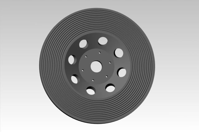
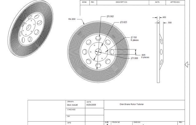
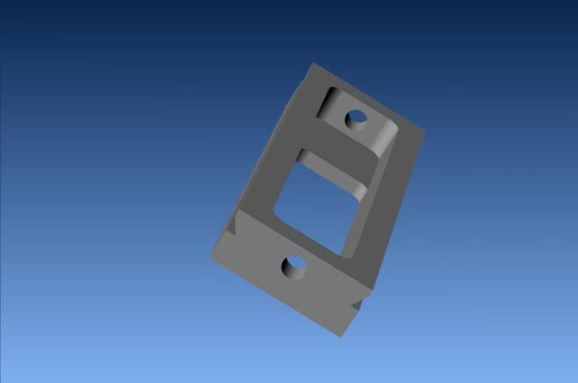
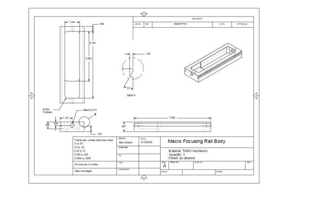
In the last year or two I have gotten fairly comfortable with Alibre' but I still remember the startup difficulties. One of the techniques that has been helpful to me is to construct a part the same as I would in the shop. In the shop, I have a Lathe and a Mill. I do not have an extruder. I try to limit my use of the solid extrude function since I can't do that in the shop. I will use it to extrude a round or flat bar that represents the raw material that I will start the actual machining process with.
After that, all modifications are done with the "revolve cut" function (lathe work) or with "extrude cut" (milling ). Rarely, I use the "loft cut" function which can also represent milling. It may not always be the quickest way to construct the part in Alibre but it is a tremendous help in planning the steps to produce the part in the shop.
For example, in your crankshaft, you start out with an extruded rod representing one end of the shaft. If you are going to make a built-up crank with the webs brazed or welded to the rod, that would be the way to start. The rod is the first piece of raw material. But the crankshaft would be made of 5 parts in an assembly.
If the part is going to be turned from bar stock, either round or flat, my first extrusion would be a piece of bar. On one end of the bar, I extrude cut two small circular depressions. One to represent the shaft center and one to represent the center of the crank throw. I would then use these to create axes parallel to the length of the bar. Switching to the side view, I would draw a rectangle and revolve cut around the throw axis. The next step would be to draw two rectangles and revolve cut them around the shaft axis.
This directly follows the cuts you would make on the lathe. There are a few things to remember. The first extrusion should be centered on the Z axis. If you are starting with a round bar, the Z axis is the center of the circle. If you are going to start with a flat bar, the rectangle should be constructed so that two sides are equal distant from the Z axis (constraint) The rectangles that are used to draw the revolve cuts must be drawn on the ZX plane, not on the face of the bar. The dimension of the shaft and the throw are determined by the dimension between the corresponding axis and the nearest side of the pattern rectangle.
I hope I made that clear. I will attach an example.
One thing I noticed on your drawing is the nice radiused edges on the crank webs. That is too easy to do with Alibre but think about what it would take in the shop. You might decide that you don't want to do that.
I hope this helps.
Jerry
View attachment crank example.AD_PRT

![DreamPlan Home Design and Landscaping Software Free for Windows [PC Download]](https://m.media-amazon.com/images/I/51kvZH2dVLL._SL500_.jpg)


