making a thread dial for a south bend 10K - cutting the gear

Home Model Engine Machinist Forum

Help Support Home Model Engine Machinist Forum:

This site may earn a commission from merchant affiliate links, including eBay, Amazon, and others.

ttrikalin

Well-Known Member
Joined
Sep 12, 2009
Messages
479
Reaction score
3
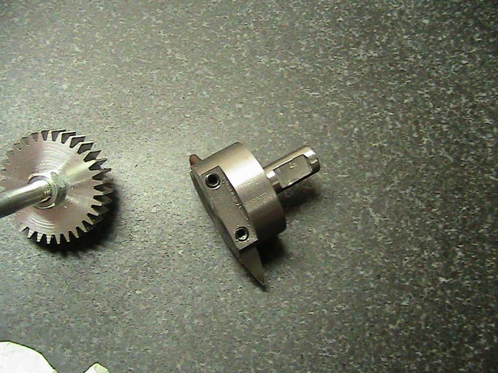
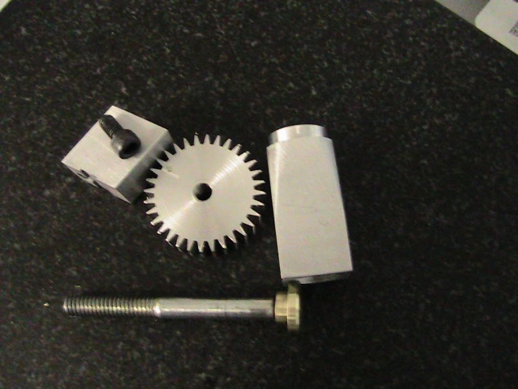
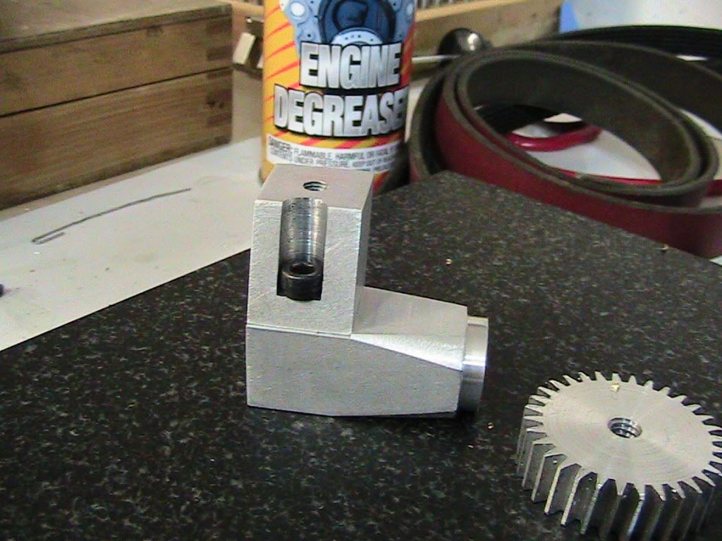
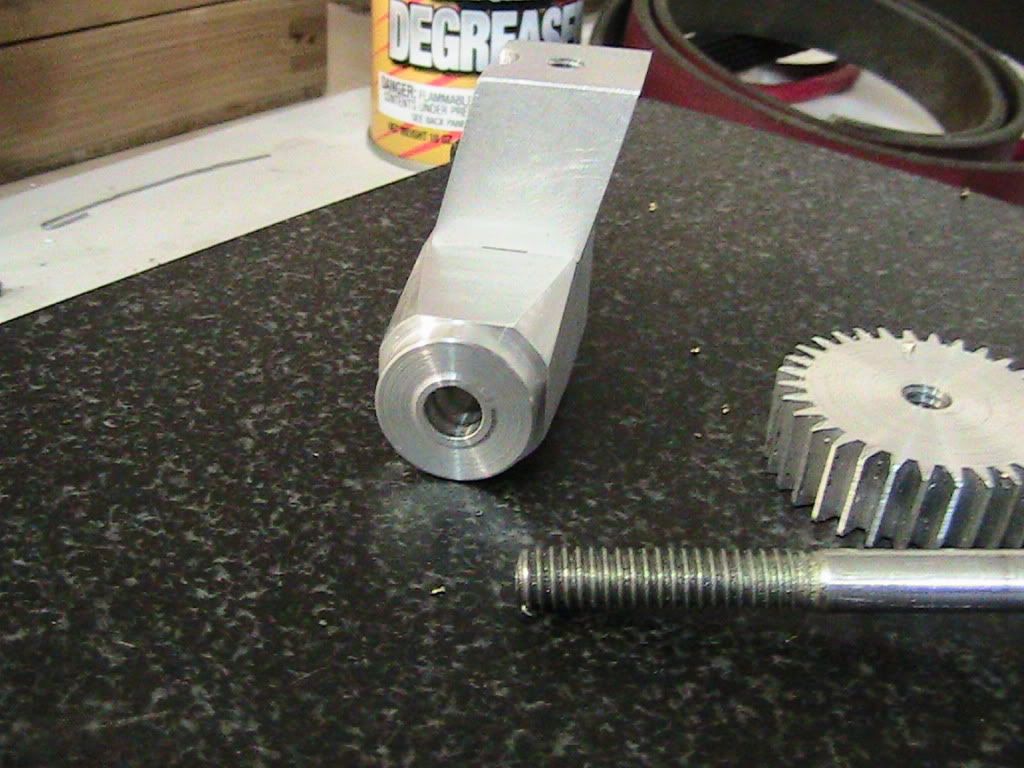
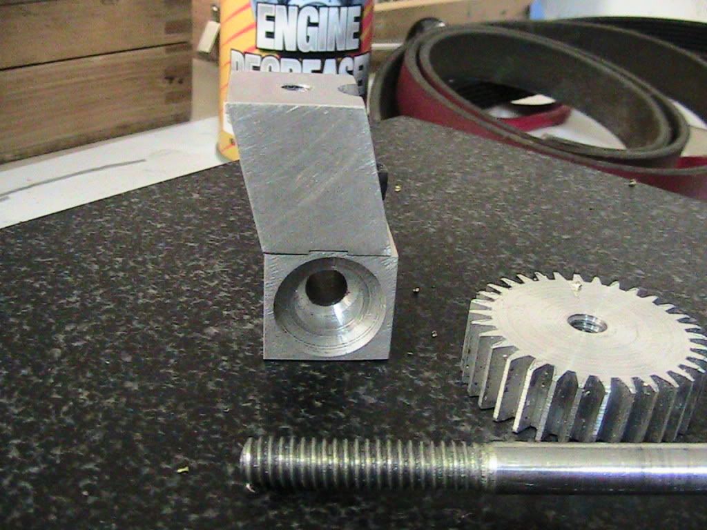
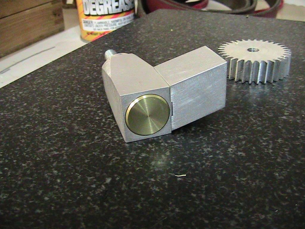
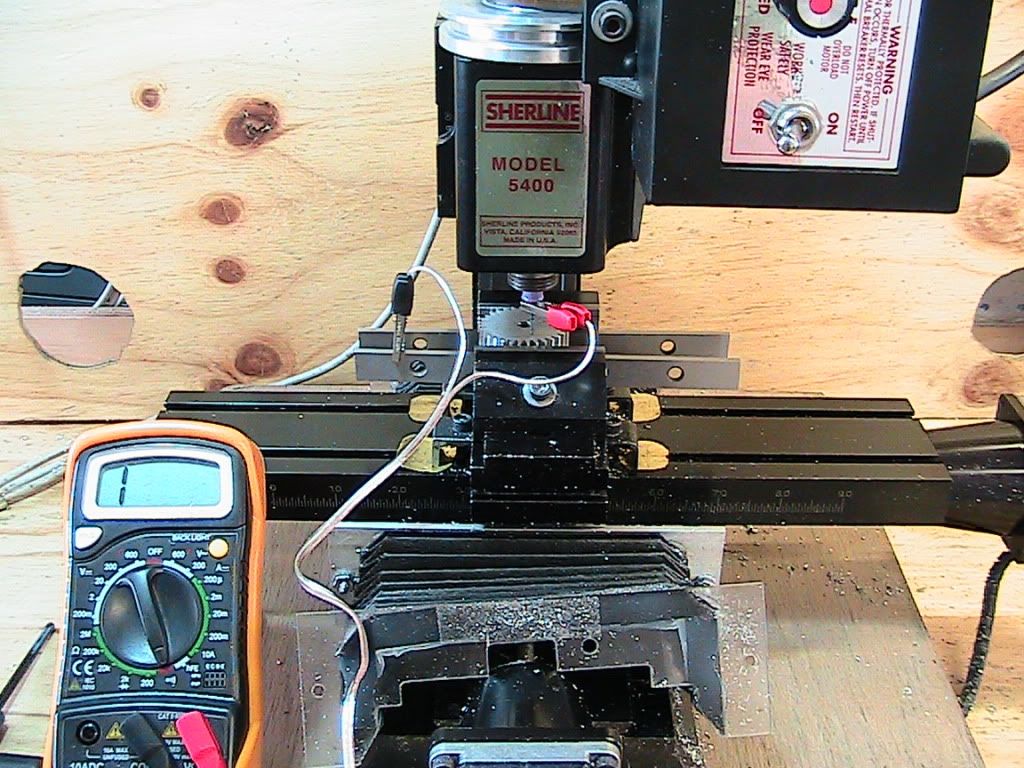
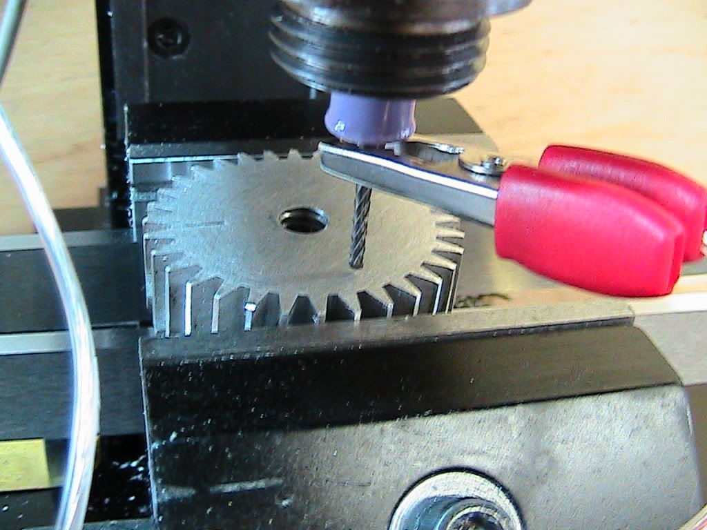
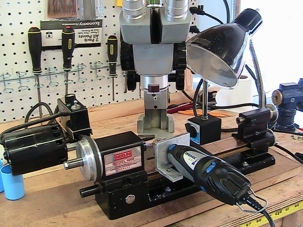
I have a SB10K and want to make a thread dial, just for the heck of it. The lathe has a 0.750" 8tpi acme leadscrew. I am about to cut the gear on my sherline mill. But before messing up, I should ask someone who does know better :)

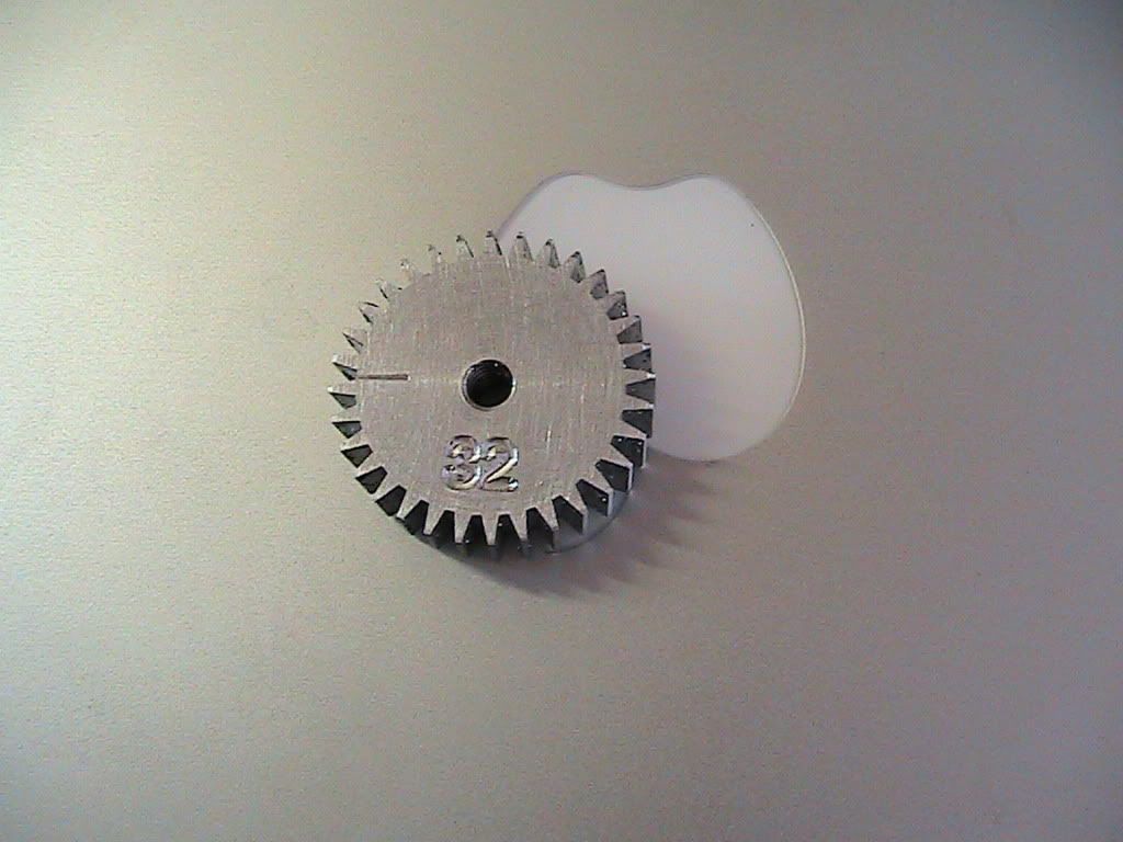
I believe I need a 32 tooth gear. I understand the logic of the thread dial, but I have never seen one or operated one :) .

I calculate the following:
1. 32 teeth * 1/8 pitch = 4" pitch circle, or 4/pi =1.2732" pitch diameter
2. the outer diameter is 1.2732 + 1/8 = 1.3982"

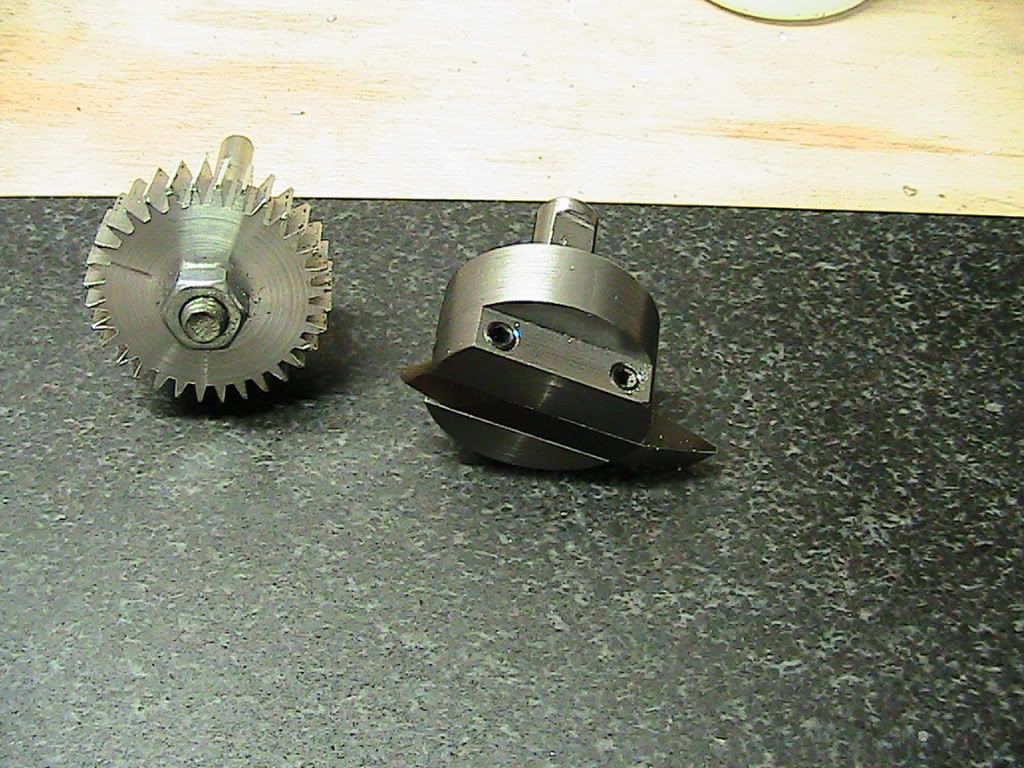
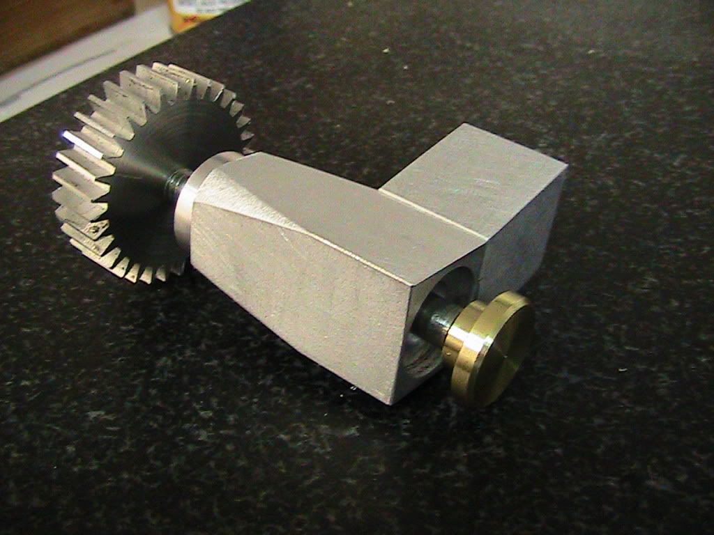
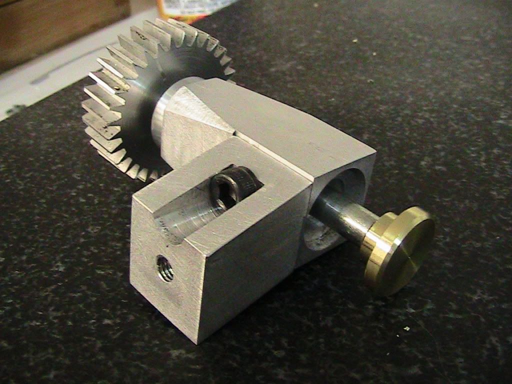
I decided to make the gear 0.400" thick - the leadscrew has a ~0.250" keyway cut lengthwise (SB's way to power the autofeeds), and I would like the thread dial's gear to be able to clear this keyway.

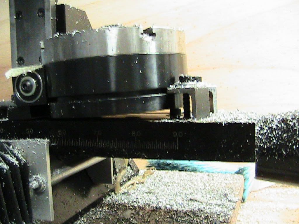
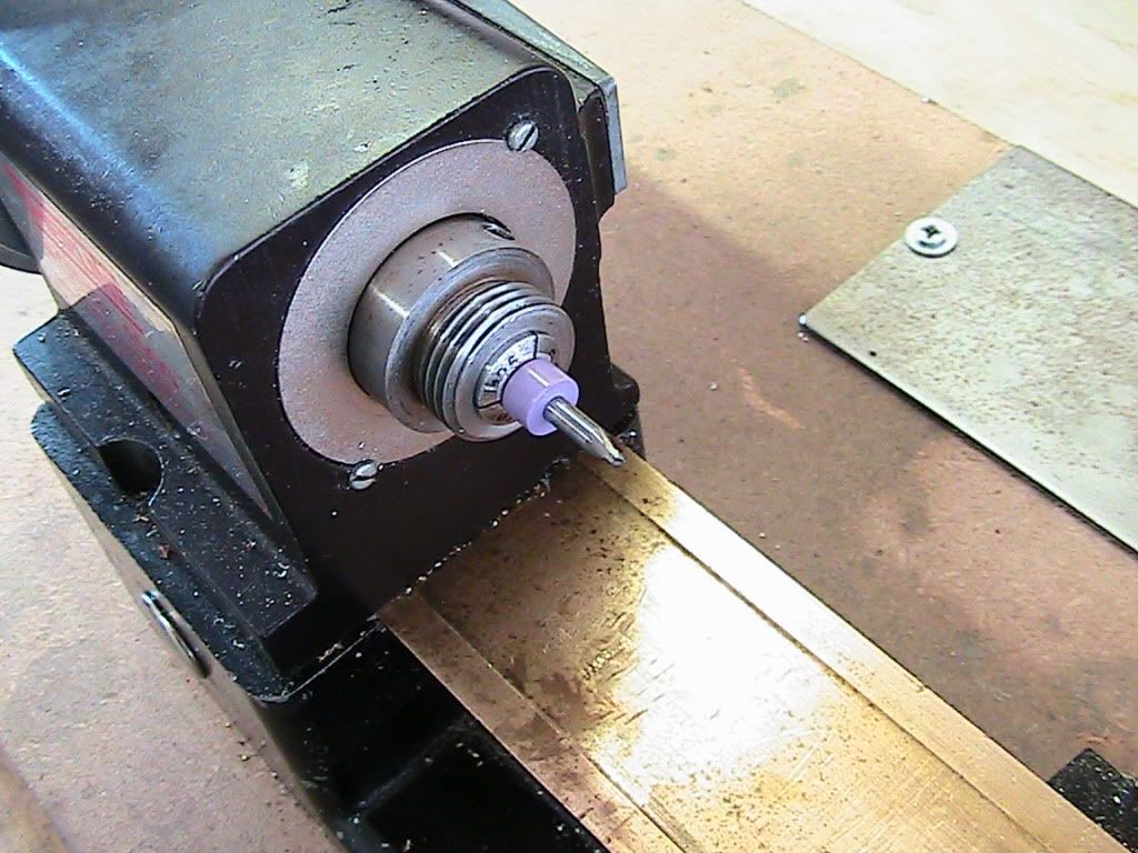
I think that straight teeth would work (no load), but the keyway may ... hob them away. So I will cut them at an angle, i.e., that of the helix of the leadscrew. And here is the question. What is the correct angle?

A. arctan(pitch / pitch diameter)=arctan(0.125/(0.75-0.125)) = 11.31 degrees? -- the angle corresponding to the "projection" of the leadscrew on a surface containing its axis, OR

B. arctan(pitch/pitch circle) = arctan(0.125/((0.75-0.125)*pi)) = 3.64 degrees?

I believe it is B, as it is the angle of the leadscrew part that is "presented" to the gear each time... But I have no other reasoning -- just this intuition, and this is never good enuf.

any thoughts?

Perhaps if I sleep on it... (the gear blank I mean)...

take care,
tom in MA

PS. since this bugger will have no resistance when turning, can't I get by with a simple gear?
 
As far as I can remember Tom, for an 8TPI leadscrew, you can use almost any old 16 straight tooth gear, as long as the gear teeth will sit into the leadscrew thread.

There is no drive pressure to talk of, so as long as the indicator turns, then that is good enough. The one on my old Atlas in fact was just pressed onto the end of the shaft.

As for wearing away the gear, you only use the drop in dial whenever you are cutting threads, so have it swinging away when not in use and I think it will last a lifetime.


Keep it simple and you can't go far wrong.

If you look carefully at the attached picture, you can just count the teeth on the gear, and that is an 8TPI leadscrew (with a drive keyway cut almost all it's length).


John


mod 07.jpg
 
thank you, john.

You are right, 16 teeth will work, I chose 32 to have an easier job when chasing the dial (it will turn half as fast, and I will work out the exact divisions on the dial later).

I believe I will proceed as you suggest and cut the gear straight.

take care,

tom in MA
 
I was thinking about doing the same thing. I have a select 1024 that came without a threading indicator. I found that the Grizzly 9249 lathe has the part for $22. So unless you just want the experience cutting the gear, this is the easy way. I also did not have the indicator, so I bought it and used scrap to make the housing and for $35. I had a new indicator.
My $.02
 
hats off -- did not even think to check other lathes. :big:

i'm itching to cut the little bugger myself - but if i do not get to it by tomorrow, I will order from papa-grizzly and do any McGyver modifications are needed.
 
ttrikalin said:
What is the correct angle?
A. arctan(pitch / pitch diameter)=arctan(0.125/(0.75-0.125)) = 11.31 degrees? -- the angle corresponding to the "projection" of the leadscrew on a surface containing its axis, OR
B. arctan(pitch/pitch circle) = arctan(0.125/((0.75-0.125)*pi)) = 3.64 degrees?

It is B.

 
All of you have been there...
I made a single point gear cutter holder out of mild steel to cut a 32 teeth gear with helical teeth that will be used in a home-brewed thread chasing dial, that will help me cut a 3/8 18 tpi thread to make a boring bar (it has two pieces that thread together) to finish that home-brewed quick change tool post.

Check the gear cutter holder and the gear off. The gear cutter holder was made from mild steel. Rather than turning a MT1 taper to match my Sherline spindle I did it fast and dirty - 3/8 straight shank with a filed flat. It is a good fit in the endmill holder.

I ground the bit free hand using an acme gage -- but I did not do a good job. Evident from the shape of the gear teeth (I also cut them deeper than needed - an honest mistake).

IMG_0274.jpg


and here

IMG_0275.jpg


Not evident in the photos - but the teeth are slanted by 3 degrees and some change. This was not necessary given the application -- but the exercise was fun. Did it with a bit of trig and a lifting screw in a tapped hole of the down surface of the sherline rotary table.

IMG_0277.jpg


Sorry for the screwey stills - these are from a video camera - the still picture camera is kaput and I have to open it up and repair the geartrain of the focusing mechanism. Which means I have to buy a new one.

:big:

and here's a video of the actual gear cutting. Up there with watching paint dry. I programmed the Y and Z axis movements, but since I never got to convert the rotary table to CNC I did the rotation manually.

[ame]http://www.youtube.com/watch?v=Y8_AUBJhIGY[/ame]

take care,

tom in MA
 
Excellent Job Tom!

Gears can be fussy, it looks like that one should work just fine!

:bow:

Dave
 
I believe it is B, as it is the angle of the leadscrew part that is "presented" to the gear each time... But I have no other reasoning -- just this intuition, and this is never good enuf.

A screw is nothing more than an inclined plane wrapped around a cylinder. Perform this Gedankenexperiment to visualize what's going on.

Make a paper 30-60-90 degree triangle from paper. Construct a cylinder with circumference equal to the length of the triangle side opposite the 60 deg angle. Wrap the triangle around the cylinder and it will form exactly one turn of a 'thread'.

Obviously, this 'thread' has a helix angle of 30 deg. The side opposite the 30 deg angle represents the advance in one revolution of the thread - what we call the pitch. The side opposite the 60 deg angle is the circumference of the 'pitch circle' by construction. Therefore the tangent of the helix angle is the ratio of the pitch to the circumference of the pitch circle.

However, in this case, with the gear serving as only an unloaded counter, a spur gear would be perfectly adequate.

 
mklotz said:
A screw is nothing more than an inclined plane wrapped around a cylinder. Perform this Gedankenexperiment to visualize what's going on.

[...]

Therefore the tangent of the helix angle is the ratio of the pitch to the circumference of the pitch circle.

However, in this case, with the gear serving as only an unloaded counter, a spur gear would be perfectly adequate.

Das is wahr, mein Herr.
I figured when I woke up with exactly the same thought experiment you suggest. Thanks, Marv.

take care,
tom in MA
 
Ok the progress till now. The design is as we go. Again, apologies for the quality pictures, they are stills from the videocamera. These are the parts I made till now. The gear is tapped 1/4-20. It will be thread on the shaft (er... bolt) I fished out of the scrap bin.

IMG_0278.jpg


The bracket of the dial and the body that will hold the shaft are held together with a 10-32 screw.

IMG_0279.jpg


Another view - this is the bottom.

IMG_0280.jpg


This is the top. The tapped hole you can barely see on the top is for mounting to the casting of the apron... Will show pics tomorrow...

IMG_0281.jpg


The brass head will be engraved tomorrow (I hope). Note that the bracket and the base are locked in place by a male and female step -- is there a formal term for this?

IMG_0283.jpg


And this is the assembly.

IMG_0284.jpg


And another view

IMG_0285.jpg


Tomorrow I'll cut the bolt to length, engrave, and mount on the apron casting. I owe a cover/housing for the gear. I enjoyed this project... My little Sherlines are wonderful...

Take care,

tom in MA
 
Looks great Tom. Can't wait to see pictures!

Dave
 
Very nice indeed Tom.

If I could make a suggestion, cut the length of your gear teeth down a little, just so that the teeth don't sit too deep into you leadscrew.

Also, if you don't know already, if you can, get a double length spring lock washer for when you mount the unit to your saddle. You grind off the sharp dig in points and put it between the unit and saddle, to allow you to adjust, by means of the holding nut, the side to side position. It acts like a very strong short spring. This will allow you to synch in the zero mark with your engraved scale when the half nuts are engaged, but still swing the unit out of mesh, or else use fine shim washers to obtain the same effect. You will see what I mean when you first come to use what you have made.


John
 
>> Note that the bracket and the base are locked in place by a male and female step -- is there a formal term for this?


Tongue and groove, perhaps?

- Ryan
 
thanks everyone for the feedback...

John, this is a very smart idea, I will visit the hardware store to see if the carry the thing. I was thinking some friction-based arrangement, but the spring is much more elegant.

Ryan, indeed - tongue and groove...

take care,

tom in MA
 
Nicely done, indeed.

One suggestion... Loctite that joint where the shaft/bolt threads into the gear lest it slip and mess up a critical thread you're cutting. If concerned about future disassembly, use the undoable (blue?) Loctite.
 
mklotz said:
Nicely done, indeed.

One suggestion... Loctite that joint where the shaft/bolt threads into the gear lest it slip and mess up a critical thread you're cutting. If concerned about future disassembly, use the undoable (blue?) Loctite.

Agreed. Will do...
 
A pointless distraction was that I wanted to engrave the number of teeth on the gear...

setting the zero Z on the mill... When the multimeter beeps, we are there. Will have to make a led for this arrangement, or hook a buzzer - the multimeter has a response time that necessitates very slow advancements of the Z axis...

IMG_0286.jpg


A closer look...

IMG_0287.jpg


And the engraved number... Duh, I had set the cut too deep, and it ended up ugly. Also, the cutter was a 1/16 endmill (V tipped, but still...). I may face it when I shave off some of the periphery of the gear to reduce tooth length (as per John), as I cut them a tad too deep.

IMG_0288.jpg


Next post will describe how I made the engraver bit for the actual dial...

take care,
tom in MA
 
I post this here as it is a continuation on how I engraved the dial... Arguably it's better suited in the break room section, or the tools section... but the moderators will indulge me...

On to make an engraver bit. I took a broken solid carbide endmill, and ground it so that it tapered to a point; then ground off half of the tip. the tip looks like half a cone when seen from the side. All operations under magnification.

I did the grinding on me dremel toolpost... See below photos of the setup and a video of the grinding... next time I'll take images under magnification...

Broken solid carbide bit in the collet...

IMG_0290.jpg


The toolpost grinder (aka dremel POS) holder.

IMG_0291.jpg


Complete setup including the stereomicroscope and lighting. All operations are performed under large magnification.

IMG_0294.jpg


Still of the diamond wheel on the rotary tool.

IMG_0299.jpg


And the video of the grinding. I took my time, usually I am faster :big:

[ame]http://www.youtube.com/watch?v=VWgfD43tPJ8[/ame]

The finishing with this wheel is not very good; the dremel has a large TIR and the disk is not for sharpening... So I honed the flat on the tip (and the cutting lip) on a fine diamond file.

As my machining webmentor Jerry G. points out, grinding should be done with the ways covered. I neglected that here... I remembered after the fact. I wiped things down, but I do not think that this minor grinding generated any abrasive dust in any quantities that can make me worry...

take care,
tom in MA
 
Back
Top