


zeeprogrammer
Well-Known Member
- Joined
- Mar 14, 2009
- Messages
- 3,362
- Reaction score
- 13
First off...I know next to nothing about a DRO. By that I mean, the features and usage of those boxes with the 7-segment displays, buttons, and nifty functions.
Second...this may not go anywhere but it has a better chance of making it if I post it. In any case, it will be slow going.
My hope is to build and install a DRO system for my X2 mini-mill and my mini-lathe.
There's been a few threads on this...so it's not new...but I hope someone finds this thread interesting and/or entertaining.
The system is based on the DRO-350... http://www.shumatech.com/
The 350 is obsolete but you can still get parts, and more importantly, PCBs.
I went to Mouser and Digi-Key and bought all the components except for the PIC processor, enclosures, cables, and of course, PCB. I also didn't get the required number of switches. I intend to use something I'm already familiar with or have access to because of my work. Initially I was going to use perfboard. But I found the costs for board, wirewrap wire, and wirewrap sockets have gone way up since I played with this stuff some years ago. I stayed awake all night thinking about all the hand wiring that would be required (I want to build two of these)...so I went ahead and bought the PCB(s) from a place that services these systems. I can connect my own processor to the PIC holes. I still need to think about cabling and enclosures.
As I mentioned, I'm building two of these. One for the mill and one for the lathe. They will not have all the nifty features of a real DRO system. I just want to be able to see the relative distance, be able to zero out, and perhaps change scale (mm/in). Having said that...the system can easily be added to. I suspect I'll keep a communication port to a PC so I can also do some software enhancing from there.
While you can simply look at the display on the caliper, I'm thinking that will be difficult to do in some cases. There's also the possibility of coolant and I need to ensure the system is covered. You can also get remote displays for the caliper but I didn't want to buy a bunch of these. Besides, I wanted the flexibility and potential that the DRO system affords.
The electronics and software will be a piece of cake for me. It's how I make my living. The rest of the system is a different story...
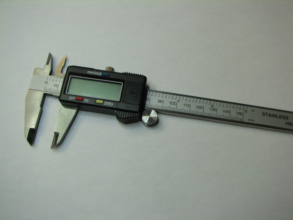
As many of you know, the system uses cheap digital calipers for inputs. So the real challenge for me is going to be modifying the caliper (metal-wise) and mounting them. The mill will need 3 and I'm thinking the lathe will also require 3 (one for the tailstock).
Here's a pic of the caliper we're talking about...
So it was time to play...
I started with an angle grinder to knock off the pointy bits. I've never used an angle grinder before. ;D And while it was somewhat successful...the cherry red glow should have been a clue. The scale bubbled up near the end.
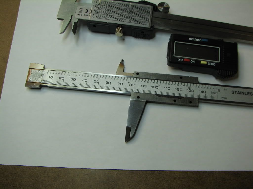
So I went to the dremel. That went pretty easily! This shot shows the display pulled off. The caliper at top shows the back. You have to peel the label off and undo the screws.
And so I continued...
I knocked off the rest of the pointy bits with the dremel. I now need a new cutting wheel for the dremel...it got worn nearly down to the shaft. At this rate I'll need 5 more.
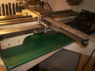
Here's a pic of what's left sitting on top of the tailstock.
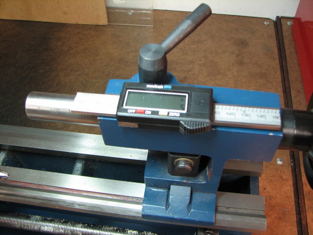
Now I need to figure out how to mount it so that no damage will occur when in use. Also want to protect against coolant.
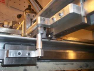
A couple of things I noticed...the display went a little nuts. Seemed to work fine in my hand...but not on the tailstock. It could be that it's too loose sitting there, it could be residue from the grinding, or it could be an electrical issue. I read somewhere that the electronics' positive is connected to the metal caliper itself...so some insulation may be required. (Note: The actual values on the scale - I cut both ends off - are not important. The electronics reads everything relatively.)
So there's the start...tips, suggestions, well-wishes are welcome.
I got tired of waiting for that guy who owes me beer (you know the one) and have procured a supply. Nor do any of you need to worry about your snacks...I got that too...and you can't have any. :big: Not even going to tell you what they are.
Second...this may not go anywhere but it has a better chance of making it if I post it. In any case, it will be slow going.
My hope is to build and install a DRO system for my X2 mini-mill and my mini-lathe.
There's been a few threads on this...so it's not new...but I hope someone finds this thread interesting and/or entertaining.
The system is based on the DRO-350... http://www.shumatech.com/
The 350 is obsolete but you can still get parts, and more importantly, PCBs.
I went to Mouser and Digi-Key and bought all the components except for the PIC processor, enclosures, cables, and of course, PCB. I also didn't get the required number of switches. I intend to use something I'm already familiar with or have access to because of my work. Initially I was going to use perfboard. But I found the costs for board, wirewrap wire, and wirewrap sockets have gone way up since I played with this stuff some years ago. I stayed awake all night thinking about all the hand wiring that would be required (I want to build two of these)...so I went ahead and bought the PCB(s) from a place that services these systems. I can connect my own processor to the PIC holes. I still need to think about cabling and enclosures.
As I mentioned, I'm building two of these. One for the mill and one for the lathe. They will not have all the nifty features of a real DRO system. I just want to be able to see the relative distance, be able to zero out, and perhaps change scale (mm/in). Having said that...the system can easily be added to. I suspect I'll keep a communication port to a PC so I can also do some software enhancing from there.
While you can simply look at the display on the caliper, I'm thinking that will be difficult to do in some cases. There's also the possibility of coolant and I need to ensure the system is covered. You can also get remote displays for the caliper but I didn't want to buy a bunch of these. Besides, I wanted the flexibility and potential that the DRO system affords.
The electronics and software will be a piece of cake for me. It's how I make my living. The rest of the system is a different story...
As many of you know, the system uses cheap digital calipers for inputs. So the real challenge for me is going to be modifying the caliper (metal-wise) and mounting them. The mill will need 3 and I'm thinking the lathe will also require 3 (one for the tailstock).
Here's a pic of the caliper we're talking about...
So it was time to play...
I started with an angle grinder to knock off the pointy bits. I've never used an angle grinder before. ;D And while it was somewhat successful...the cherry red glow should have been a clue. The scale bubbled up near the end.
So I went to the dremel. That went pretty easily! This shot shows the display pulled off. The caliper at top shows the back. You have to peel the label off and undo the screws.
And so I continued...
I knocked off the rest of the pointy bits with the dremel. I now need a new cutting wheel for the dremel...it got worn nearly down to the shaft. At this rate I'll need 5 more.
Here's a pic of what's left sitting on top of the tailstock.
Now I need to figure out how to mount it so that no damage will occur when in use. Also want to protect against coolant.
A couple of things I noticed...the display went a little nuts. Seemed to work fine in my hand...but not on the tailstock. It could be that it's too loose sitting there, it could be residue from the grinding, or it could be an electrical issue. I read somewhere that the electronics' positive is connected to the metal caliper itself...so some insulation may be required. (Note: The actual values on the scale - I cut both ends off - are not important. The electronics reads everything relatively.)
So there's the start...tips, suggestions, well-wishes are welcome.
I got tired of waiting for that guy who owes me beer (you know the one) and have procured a supply. Nor do any of you need to worry about your snacks...I got that too...and you can't have any. :big: Not even going to tell you what they are.
")