Elmers Engine 2x#33

Home Model Engine Machinist Forum

Help Support Home Model Engine Machinist Forum:

This site may earn a commission from merchant affiliate links, including eBay, Amazon, and others.
The Locomotive "eccentric" you show may not put the line of the valve rod far enough out to the side and would better suit a top mounted valve chest, Maybe Richard can show a sketch of what he has in mind ?

95mm flywheel would look about right but you would need to cut out the base the pair of engines are standing on.

The #33 is quite a similar layout to a little long out of production Stuart engine that I'm currently working on.

pro 3d.JPG

20230214_191921.jpg
 
But that's good to plan ahead for exactly what you want. When I was in college (last week) the professors would always like what I proposed as a project, however, the first thing they would say is "Draw it up and let me see it". Of course to a young whipper snapper that is throwing cold water on two dogs itting. But now in my old age (12 years old) I see that they are right. MY projects were never really thot thru properly and doing a drawing clarified what I had not even considered. So you seem to be thimpfking carefully about your intentions. Good

My son is going thru that stage but he only makes a poor sketch and it barely gets him to see his mistakes or omissions. Him and I want to make a couple revolvers or some other kind of hand guns but we have no drawings. One of the places I visit somethimes is John-Toms. I thimpfk they have pistol and guns in general plans for sale. Does anyone know of other gun plans for sale?
Where I am reading that thread probably already puts me half in prison. :cool: I stick to models.
 
The Locomotive "eccentric" you show may not put the line of the valve rod far enough out to the side and would better suit a top mounted valve chest, Maybe Richard can show a sketch of what he has in mind ?

95mm flywheel would look about right but you would need to cut out the base the pair of engines are standing on.

The #33 is quite a similar layout to a little long out of production Stuart engine that I'm currently working on.
I will stick to the internal version for now. The plan B is to move the valves to the top. So the "loco" thing is just the basic principle. to explain to myself what Richard ment.
I reduced the "virtual" flywheel diameter a bit, because after 3d printing one it looked a bit too large. The new size will still require a small cut out of the "floor" but not as large. Computer sais it will weigh around 230 g.

Did you machine the complete base out of a big block, or did you just clean up the top with the milling machine? It looks very "unrusty".

Greetings Timo
 
Last edited:
Started with some 40 x 60 steel which I roughed down on the manual mill to 53 x 34 x 131 long and them machined from that, all sides have draft angle so it looks like a casting. second setup to do under the cylinder support
 

Attachments

  • pro setup.JPG
    pro setup.JPG
    40.8 KB
  • pro setup 2.JPG
    pro setup 2.JPG
    44.9 KB
But that's good to plan ahead for exactly what you want. When I was in college (last week) the professors would always like what I proposed as a project, however, the first thing they would say is "Draw it up and let me see it". Of course to a young whipper snapper that is throwing cold water on two dogs itting. But now in my old age (12 years old) I see that they are right. MY projects were never really thot thru properly and doing a drawing clarified what I had not even considered. So you seem to be thimpfking carefully about your intentions. Good

My son is going thru that stage but he only makes a poor sketch and it barely gets him to see his mistakes or omissions. Him and I want to make a couple revolvers or some other kind of hand guns but we have no drawings. One of the places I visit somethimes is John-Toms. I thimpfk they have pistol and guns in general plans for sale. Does anyone know of other gun plans for sale?
Google "Childs Camper Pistol"
 

Attachments

  • post-6-23240-Childs_Camper_Pistol.pdf
    658 KB
Started with some 40 x 60 steel which I roughed down on the manual mill to 53 x 34 x 131 long and them machined from that, all sides have draft angle so it looks like a casting. second setup to do under the cylinder support

That is a pattern.
Now cast it.

You are officially a pattern maker.

.
 
No it's CNC machined to finished size, I'd need to add machining allowances and shrinkage allowance to pull a casting from it. I'd also want to hollow it out a bit underneath if making a casting as the foundry charges by weight.

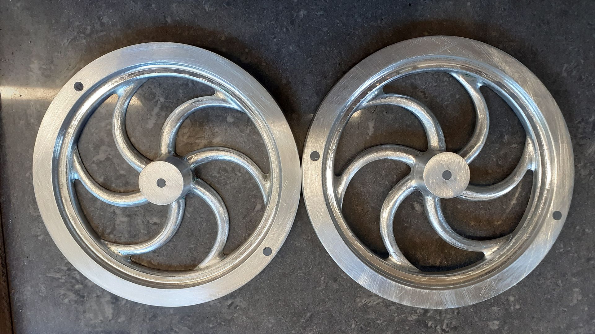
Did have these arrive earlier in the week and they were made from a pattern that I made

nattie flywheels.JPG


20220724_083912.jpg


And I just e-mailed this half pattern to someone this afternoon which is currently 3D printing

Derwing Pulley Half.JPG


Should look something like this when finished, replacement for a missing pulley from a Redwing engine.

redwing pulley.JPG
 
Green twin, have you met the English that use a "Rubber" to mean "pencil eraser"? Or the bloke who offered to help the American lady to "wash-up" - thinking she was going to clean the dirty plates, pots and pans?
2 nations divorced in thinking, sharing common words.

To us Old nation folk "the tea party " was a convivial meeting of friends sharing a cup of brewed dried tea plant leaves, with a few small sandwiches and cakes.
But the upstarts in Boston decided at their "Tea party" that they should stop paying taxes to "Britainy" - which we think is a region of Northern France? The taxman never forgets, but simply adds interest to the outstanding tax bill...
K2
 
parts for the base, the one on the right is scrap. Flipped the part wrong from right to left, so all the holes from the underside ended up in the wrong positions, a broken tap completed the Friday evening. I skipped workshop on Saturday.
K1600_DSC00108.JPG
:cool:
 
Sorry to hear of your "misplaced holes, etc." - But I sympathise having done that job before.... "There but for the grace of God, ... " etc. Sometimes we miss that "Grace" in the workshop... There must be a little workshop divil on our shoulders that whispers, "It'll be alright, just do it there, now."
I would have cheated and just drilled the right holes then called the spare holes "spares for future use", or "lightening holes"!
K2
Yes, getting used to my clumsiness, I will end up with 60 useable parts and several (hopefully less than 49) scrapped ones. .... :)
K1600_DSC00109.JPG

Next pair of parts, lower parts of base without the "anchor lugs" (someone called them like this).
 
Clumsiness and low frustration resitance and the cursed part

1st cylinder I clocked the flange holes wrong, noticing that the bolts will interfere with the steam hole
2nd cylinder I broke the drill in the cast iron :-( and had to start over.
3rd one got damaged "parting off" with too sketchy setup......
I got a bit frustrated and tossed the things in one of the many dark corners of my "work cave"

Again,.... milling the start of the steam hole with a 1 mm endmill, to get the hole started. Then drilled few mm with a short carbide drill. Finished to final depth.... one hole finally done. The small vise in bigger vise to get angle right.
With all the steam passages finally done, and a collection of scrap cast iron cylinders, I was sort of back :)
on track.

cursedpart.JPG

I had the "smart idea" to thread the cranks on the crank axle. After having made the parts I remembered that the cranks need to be at a certain angle relative to each other! ..... :eek: 😵‍💫
I just tried and luckily due to pure coincidence the cranks ended up at roughly 90 deg when tighened good.

side view.JPGtop view.JPG
Cranks screwed on with right hand thread on the right side; left hand thread on the left side. The idea is they should tighten when running under "load". It will probably never have to work (means moving only).
The valve adjustment on the inside turned out to be doable. I adjusted the valve first on each side separately, before mounting the two halves on the base.

... To Do, but probably will leave it as is... and start other projects :cool:

  • piston rings ( it runs without any, but is not a torque miracle)
  • paint ( I think I probably keep the metal parts as they are for now)
  • attending all the leaks to improve everything. ( it runs on compressed air as is, but I doubt it can be used with steam, because it blows everywhere)
  • making proper piping to replace the quick and dirty plastic tube.


Greetings Timo
 
Last edited:

Latest posts

Back
Top