220V single phase motor install and wiring

Home Model Engine Machinist Forum

Help Support Home Model Engine Machinist Forum:

This site may earn a commission from merchant affiliate links, including eBay, Amazon, and others.
Pat J said:
In Steve's diagram, the motor terminals are listed at the top and bottom.

The switch terminals are in the middle, and the switch terminal T1 label should read 2, and the switch is terminal T2 should be labeled 4.

They should be but in the diagram for the switch and the stickers on the switch in the photo's show them labled as I drew them. There is no 1, 2, 3, or 4. I labled them on the drawing the same as they are so there would be no confusion for Dave at hook up time.


Dave, I got to hit the sack. I am more than confident that if you follow the drawing in #34 and tie T2 and T3 together and send them to 7 or 11, you will have a good result. Don't forget to remove that one jumper also.

Cheers!

Steve
 
I am confident too Steve....

Thanks to all....I'll hit the sack too.

Dave
 
Dave and all,

I am not so willing to abandon the instruction sheet that came with a brand NEW switch and start modifying it. I figure that the engineers that made the switch and drawing know what they are doing.

Anyway after reviewing the photos of the switch Dave posted I could see that terminals 8 & 6 and 12 & 10 were jumpered in photo 2. The third photo shows that L2, 7 and 11 are jumpered. The last photo shows that L1, 5 and 9 are jumpered.

That is exactly what the ACI diagram shows for jumpers. Here is my version of the switch drawn in all 3 positions with the contacts open or closed as in the ACI diagram.
DRUMSWITCH.jpg


The only other thing shown on the ACI diagram is the main windings connected to T1 and T2 and the Aux. winding is connected to 8 and 12.


I could not locate a motor diagram on the web to explain the terminal markings of a dual voltage capacitor start single phase motor so I checked my school book from the sailor factory. I redrew the drawing and added "peckerhead" as just like Dave it makes me laugh to type it.

Single_phase_motor_hubert_5-9-h.jpg


Now we have knowledge of the motor terminal markings except for the overload protector.
Here is my answer based on my research of the subject.
ACI_switch__motor.jpg


Cheers Dan
 
Dan

If you look at the nameplate for Steamers motor you will see that L2 should never be hooked to anything except T4 for both forward and reverse. The jumper from L2 to 7 has to come out or you will permanently connect it to T2 and T3 and god knows what else when switched to forward or reverse.

That switch can be modified to work with MANY types of motor when connected properly.
 
Steve,
Just as there is more than one way to wire a switch there is more than one way to wire a motor. L1 and L2 are red and black and interchangable.

From Hubert there are two ways to reverse a single phase motor reverse the main windings or reverse the starting windings. In this case the far ends of the main windings are T1 and T4 we can reverse them to reverse the motor or reverse the start windings at T8 and T5.

The motor needs to be checked to see if it agrees with Hubert which is simple T1 and T2 should be half of the main winding and T3 and T4 should be the other half so they should have the exact same resistance. A similar magitude of resistance should be found on T8 and T5 for the start windings. When T3 and T2 are jumpered in the peckerhead the resistance between T1 and T4 should be exactly double the half main winding resistance.

My answer is based on my belief that the motor internals match Fig 5-9. If this is not the case then my answer will not work.
Dan
 
OK guys,,, I don't mind disagreement....as Pat's tag line stated, I think it makes the synapse's fire a little harder for a little longer...

That said....lets be cool, calm and collected about all this shall we?
I have really enjoyed the team effort thus far. I have found it very rewarding.

Dan, Your efforts are obviously and evidentally generous!, and your convictions are pure no doubt. I thank you very much for your hard effort. That was a lot of drawing,posting, and prose. I do appreciate it! :bow:

That said, please don't feel singled out, as my following comments are to the general public, not just you.

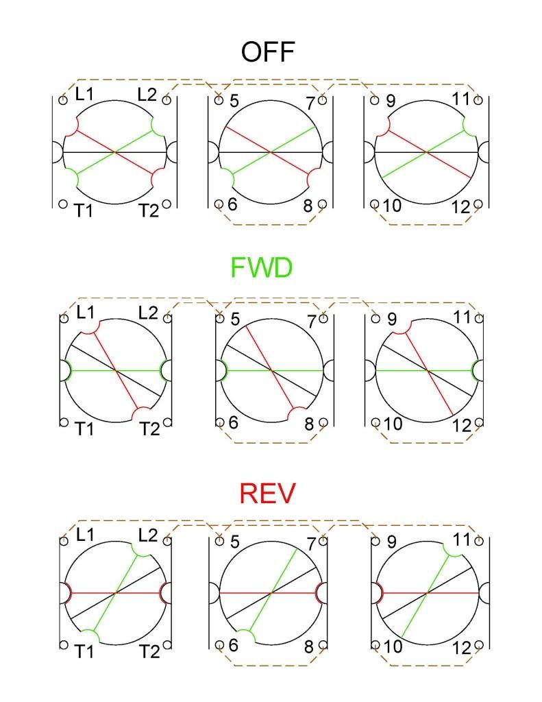
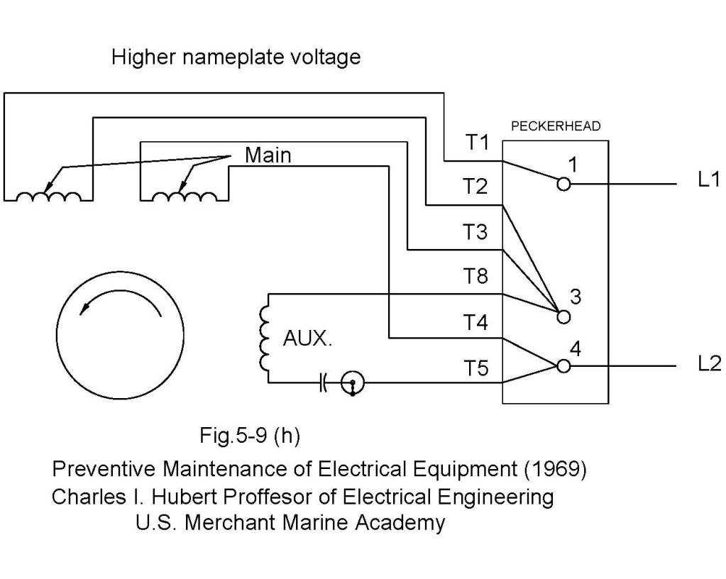
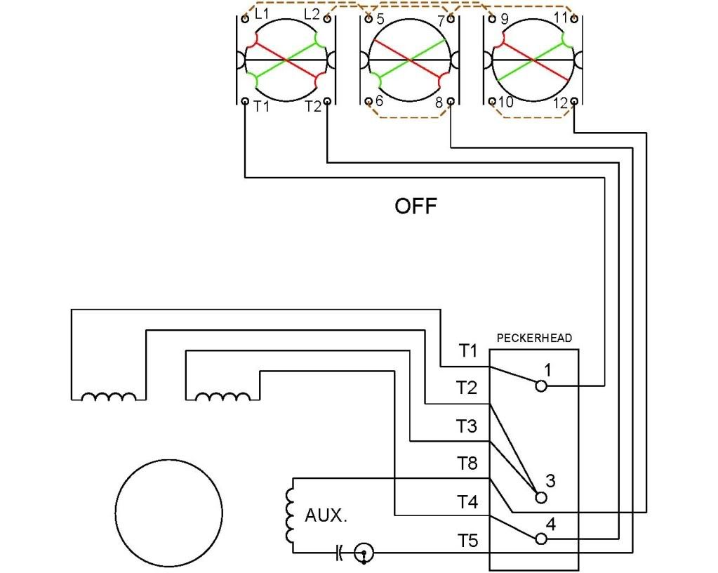
I personally ohm'd out the diagram that Steve provided, with the jumper removed per his instructions and I agree that his scheme works, and I am satisfied that the switch is completely open with my switch off ,wired to my motor. I will not vouch for any other motor or wiring scheme for anyone else.

I checked all other combinations for shorts or opens that would contradict the diagram provided. I found none.

That said, It is now MY responsibility to VERIFY this via what ever other test deemed required and or prudent to prove that I have a safe work environment for myself. THE RESPONSIBILITY IS NO ONE ELESES.

If anything is wrong from here on in, it's MY problem and no one Else's!

I would further point out to anyone else reading this thread, that this applies to you also. YOU are responsible for YOUR actions regarding wiring motors, hangliding, feeding pigeons or what have you!

Your mileage may vary, professional driver on closed course...yada yada yada. ;D


A warm and sincere Thankyou to Dan, Pat, and Steve, you guys make this such a great forum, and why I come here just about everyday.


Sincerely,

Steamer
 
Here is my quote from Post #11

With multiple responders (maybe all equally qualified) these threads can become very confused since there may be more than one way to do the wiring correctly.
 
Thanks Pat J :bow: :bow:

"Let's Be CAREFUL Out There"

Best Regards
Bob
 
Yoo Steve!


Works great Buddy! Thankyou! :bow: :bow: :bow:

Dave
 
Dave,
I am glad it worked I never doubted Steve's solution.

It was a fun intellectual exercise for me as I had to know why the switch came set up the way it was. Designers of switch gears think in millions of units and look for the most efficient solution which seems to be a 4-wire solution.

Information on the internet is handy and free but there is a lot of garbage represented as fact.

I highly recommend the book I mentioned for electrical motors of any type. My copy is a bit worn from many trips in the bottom of my sea bag. If you have ever packed a sea bag more than once you will know that it has to be a useful book to be included. It is the only engineering book that I would always pack.

I checked the internet for a new copy and found several other books by Charlie Hubert that are not on my shelf, and the updated version of the Electrical Bible for the US maritime industry has a 2002 date on it and the used price is about $100. It is now on my wish list.

Charlie Hubert is one of the brightest men I have ever met personally. I had the enjoyment of being his student. If he is still with us he is really old now because he was in his late 50's or older when I was at Kings Point.

I have to describe him and tell a story or two about him. He is a slender frame man with a full head of white hair. He wore a standard white oxford shirt with a different bow tie every day. His manner was very youthful and jolly. You almost expected that his bow tie would just start spinning at any moment. He would walk into the room with no notes and lecture and field questions off the top of his head. I never saw him stumped or even heard any story of him ever being stumped by a question. I asked him several and never got him. He asked me a few and I did not have answers. Once he called on me to ask if I had any questions and when I said that I did not his response was "Why not?" to which I had only a lame "I don't know." The last time I saw him I had been sailing a few years. He was writing a new book and he asked me if I had seen anything that should be included in the book and again I only had a lame answer.

He gave fair tests but you needed to know the material. There was always a lot of stress at KP and tests and especially finals were the pits. Charlie had a way to defuse this a bit. He would give helpful hints from Uncle Charlie. The rules were simple. You had to have something on the paper to where you got stuck. He would look over the work, add the next step in red, and take off the points he thought the clue was worth. I never had to use the service but at least once I should have because I got the treasured laughing zero. The laughing zero was reserved for a really good effort but TOTALLY wrong.

Dan

 
steamer said:
Yoo Steve!
Works great Buddy! Thankyou! :bow: :bow: :bow:


Great to hear!! Now for the hard part. Make sure you have all the wiring in pipe and in boxes. Make it neat tidy. If you look thru the clutter you can see that I have a switch that serves as a service disconnect for the phase converter and the mill. The junction box contains the capacitors for the phase converter and the converter sits on rubber pads to keep the noise down and keep it in one place.

I guess the point of all the rambling is, NO EXPOSED WIRES!!

Now you can get back to the fun stuff!!!!


DSCN0746.jpg
 
It is Alive!

With all the features I was looking for.....now for the high speed spindle!

Thanks guys!


Dave
 
Back
Top