Zx45 wiring question

Home Model Engine Machinist Forum

Help Support Home Model Engine Machinist Forum:

This site may earn a commission from merchant affiliate links, including eBay, Amazon, and others.

Naiveambition

Well-Known Member
Joined
May 15, 2012
Messages
369
Reaction score
95
Ive been trying to read Chinese wiring diagrams and well.....:wall::wall::wall:


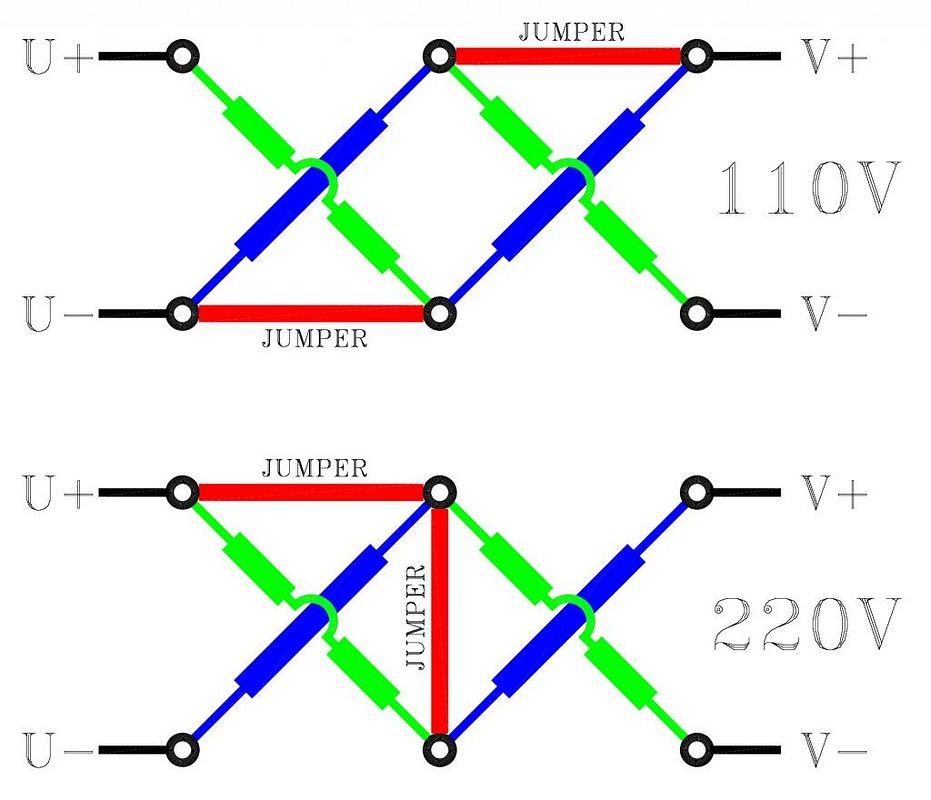
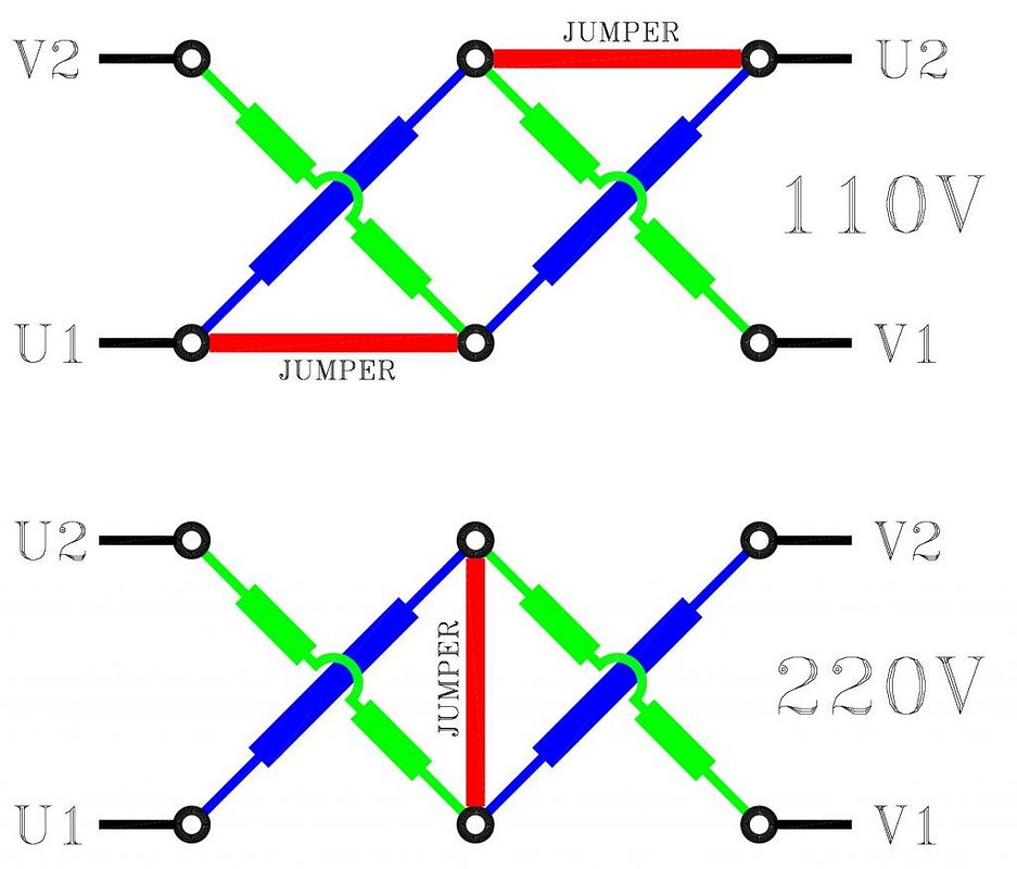
I've found a better version on bolton tools website. I am trying to hook up to 220v, and machine is now 110v.

From the book it gives pics of the on/off switch from top and side angles. I understand how to switch the motor controller to 220v, so my question is would you also have to rewire the on/off forward/reverse switch also.?


The manual has me thinking that the switch would be wired both voltages and just change the motor controller contacts.

I can't post the website or the PDF. so here is a pic of what I have, same as manual. This is the top rear of the switch.

Thanx for any help

image.jpg
 
As you can see just the jumpers are moved to make the change, so.... Do I change switch wiring also?

image.jpg
 
Can anyone with electrical knowledge please decipher this for me. Reverse is for regular milling direction but it does not show how to hookup forward. I am missing how the U2 lead is wired in so I will have tapping abilities.

As you can see in the photo it does not give a path for U2. On any other voltage including three phase all wires are used. When I try to switch to forward the motor hums but does not turn. Sounds like it is missing the other leg.

. The other previous posted photos show all wires hooked up but these are different motor wiring diagrams. Also in other photos you will notice that the bars you change for 220v only use one. My diagram shows you to make an "L" with them.

Any help is greatly appreciateed

image.jpg
 
I downloaded the photo and zoomed in. I would guess U2 should be next to U1 (top right terminal in photo) - that connection appears to be missing from the Chinese legend plate.

A better photo of the aluminium connection diagram plate will help - I can't read it as is.

Also your jumper positions don't match your prior post ? the "L" jumper links in your last post do match the plate - so I presume the connections are as follows :-

EMOTOR.jpg


Take all jumpers and connections off - there should be four sets of windings as per above (generally two centretapped pairs for 220/100V use).

I have used plus and minus symbols so you can follow how the power runs through the coils as parralell pairs for 110V and in series for 220V but when you change U+ now pairs with V- so this will probably reverse the motor as well (maybe not but possibly)

One set of windings will be connected via a starting capacitor by changing which winding is connected to the capacitor you will change the rotation of the motor.

All 4 wires must be used. One leg has the capacitor in it - by switching around it will reverse - with the missing wire it will not start and just hum as only one set of windings is energised.

You should not have to change the switch wiring.

Its getting late here and I'm losing the plot - I can see errors in my drawing - but I presume you will get the general idea and come right. If I get a moment I'll try and rectify this.

Regards,
Ken
 
Here's the better photo of the motor plate. If you notice the connections are vertical and the diagram is horizontal. But the letters on the plastic block are as follows.

U1. Z2

V1. U2

Z1. V2. This is vertical position of connection plate which is in photo of previous post

Per diagram jumpers are between v1 to U2 and U2 to Z2. As you see in this posts photo it does not give a path for U2.

I have It hooked up now using this plate diagram, and runs fine using 220v running in reverse but am still missing the last leg and/or forward.

image.jpg
 
Need to look at the wires going to the capacitor. Typically there are 3 wires running from the motor. One is common or neutral for 110VAC or L2 for 220VAC. The other 2 wires connect to the capacitor. Which ever side of the capacitor L1 connects to decides the direction of rotation.

Some motors only connect the capacitor for starting. On those, the motor runs very hot if the start cap is left connected.
 
Ok we are hooked up an running both ways. Talked to engineer at bolton tools and he sent this photo for hookups.

Still seems wrong according to motor plate diagram. Only thing I can think of is that this plate also goes on a one direction motor, which makes sense for typical 3 wire hookup. Also noted is that the forward/reverse is now correct. China hmmm.?:wall::wall::rant::rant:

Anyways I will finish this thread out saying thank you to all who responded. That really is the beauty of this website ( besides the motors of course) is that there are so many people willing to offer their time and knowledge.

So here is the photo to help any others that run into this issue. He did mention that wire colors could be different so follow the letter on the wires

Vertical position of plate top to bottom

U2. V2

--bridge--

V1. U1

image.jpg
 
I was in the process of responding vis :-

EMOTOR1.jpg


The legend plate on your machine is wrong - this is the only configuration I can come up with that works.

Note: No jumper may "short" a coil whether in use or not (that was the fault I spotted in my earlier post) and the jumpers shown on your legend plate don't work or allow a reversible configuration.

The 110V jumpers put the coils in parallel - for 220V you only have to remove them (they are placed across a neutral connection - someplace to keep them).

The fact that the legend plate is wrong is shocking - but the sort of thing I've come to expect from Chinese manufacturers.

Regards,
Ken
 
It is a wonder these machines are allowed into the country with wiring diagrams totally incorrect. Probably needs someone to be electrocuted before the authorities react
 
It is a wonder these machines are allowed into the country with wiring diagrams totally incorrect. Probably needs someone to be electrocuted before the authorities react

I totally agree with you. I'm in Canada blew a motor on one of my lathe it was under waranty fine. The supplier went thrue 4 motors before getting one that would match the diagram:mad::mad::mad:

cheers
 
I downloaded the photo and zoomed in. I would guess U2 should be next to U1 (top right terminal in photo) - that connection appears to be missing from the Chinese legend plate.

A better photo of the aluminium connection diagram plate will help - I can't read it as is.

Also your jumper positions don't match your prior post ? the "L" jumper links in your last post do match the plate - so I presume the connections are as follows :-

EMOTOR.jpg


Take all jumpers and connections off - there should be four sets of windings as per above (generally two centretapped pairs for 220/100V use).

I have used plus and minus symbols so you can follow how the power runs through the coils as parralell pairs for 110V and in series for 220V but when you change U+ now pairs with V- so this will probably reverse the motor as well (maybe not but possibly)

One set of windings will be connected via a starting capacitor by changing which winding is connected to the capacitor you will change the rotation of the motor.

All 4 wires must be used. One leg has the capacitor in it - by switching around it will reverse - with the missing wire it will not start and just hum as only one set of windings is energised.

You should not have to change the switch wiring.

Its getting late here and I'm losing the plot - I can see errors in my drawing - but I presume you will get the general idea and come right. If I get a moment I'll try and rectify this.

Regards,
Ken
Hello I am new to this forum,
I'm having similar issues to the same condition.
2 horse power to 220 motor.
Able to get one direction but not the other (reversing)
I've tried many different scenarios with no luck
Would you or anybody in this forum be able to help my situation.
Here's a picture of the name plate of the motor.
 

Attachments

  • 20200913_131812.jpg
    20200913_131812.jpg
    178.1 KB · Views: 165
Again a diagram that doesn't make a lot of sense - it shows two capacitors.

Basically you have two sets of windings - one is in series with the capacitor - that causes a change in phase angle by 90° so the motor turns.

By swopping the cap to the other winding you reverse the direction. For such use the windings are offset by 90° the motor works equally poorly in both directions.

Remove all connections and identify the two windings - the rest should be straightforward.

However the phase shift is never going to be 90° so they shift the angle between the windings - so the motor will not work as well reversed.

So they have used a bigger capacitor for one of the rotations to offset this ?

If there are two capacitors then they are in series one with each winding - one will be shorted for forward and the other for reverse (not both together - that will just hum - get hot - all the blue smoke put there by the manufacturer comes out).

If you get the 150UF where the 20UF should be one direction will be much less powerful that the other - it will overheat but slowly so it won't just blow up in your face.

Diagnostics at a distance is always a little too much guesswork for my liking - I hope this helps.

This could be further complicated by an internal centrifugal switch which disconnects the "start" winding - you normally hear a distinct "click/ whirrr' sound as the motor stops - I haven't seen that used for years so its unlikely.

Dope out the internal connections and get back to me.

Regards, Ken
 
Last edited:
Again a diagram that doesn't make a lot of sense - it shows two capacitors.

Basically you have two sets of windings - one is in series with the capacitor - that causes a change in phase angle by 90° so the motor turns.

By swopping the cap to the other winding you reverse the direction. For such use the windings are offset by 90° the motor works equally poorly in both directions.

Remove all connections and identify the two windings - the rest should be straightforward.

However the phase shift is never going to be 90° so they shift the angle between the windings - so the motor will not work as well reversed.

So they have used a bigger capacitor for one of the rotations to offset this ?

If there are two capacitors then they are in series one with each winding - one will be shorted for forward and the other for reverse (not both together - that will just hum - get hot - all the blue smoke put there by the manufacturer comes out).

If you get the 150UF where the 20UF should be one direction will be much less powerful that the other - it will overheat but slowly so it won't just blow up in your face.

Diagnostics at a distance is always a little too much guesswork for my liking - I hope this helps.

This could be further complicated by an internal centrifugal switch which disconnects the "start" winding - you normally hear a distinct "click/ whirrr' sound as the motor stops - I haven't seen that used for years so its unlikely.

Dope out the internal connections and get back to me.

Regards, Ken
20200914_181355.jpg
 
Here's a picture of the switch controlling it
 

Attachments

  • 20200913_132850.jpg
    20200913_132850.jpg
    130.5 KB · Views: 176
Back
Top