


Those of you who have installed and used the optional power feed unit for your Sieg X3 or SX3 (Grizzly G0619) bench mill, have probably been disappointed to find that it imparts a most aggravating drag on the x-axis feed screw. This is due to the fact that, unlike the power feed units generally found on industrial-sized mills, the gearmotor of Sieg unit remains coupled to the feed screw even when the power feed unit is turned off. The result is that manual movement of the table, particularly fine movement, where a measure of feel is desired, is rendered nearly impossible.
To overcome this disadvantage, I installed a clutch (of sorts) between the x-axis feed screw of my G0619 mill and the power feed unit. Thus, when I want to move the table manually, the power feed unit is simply uncoupled from the feed screw. Since completing this modification, several others have expressed a desire to equip their mills with such a device. To that end, I offer the following drawings and pictures that I used in modifying my own mill. While not the most simple undertaking, neither is it particularly difficult, requiring only modest machining skills, access to a lathe (ideally, one that will pass a 5/8 diameter rod through the spindle) and a willingness to make a slight modification to your mill. Probably not the ideal project for the rank beginner, but if you have some machining experience, and have a good mechanical aptitude, you shouldnt have any problems.
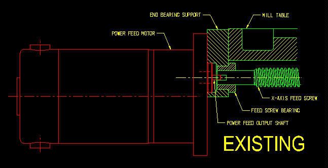
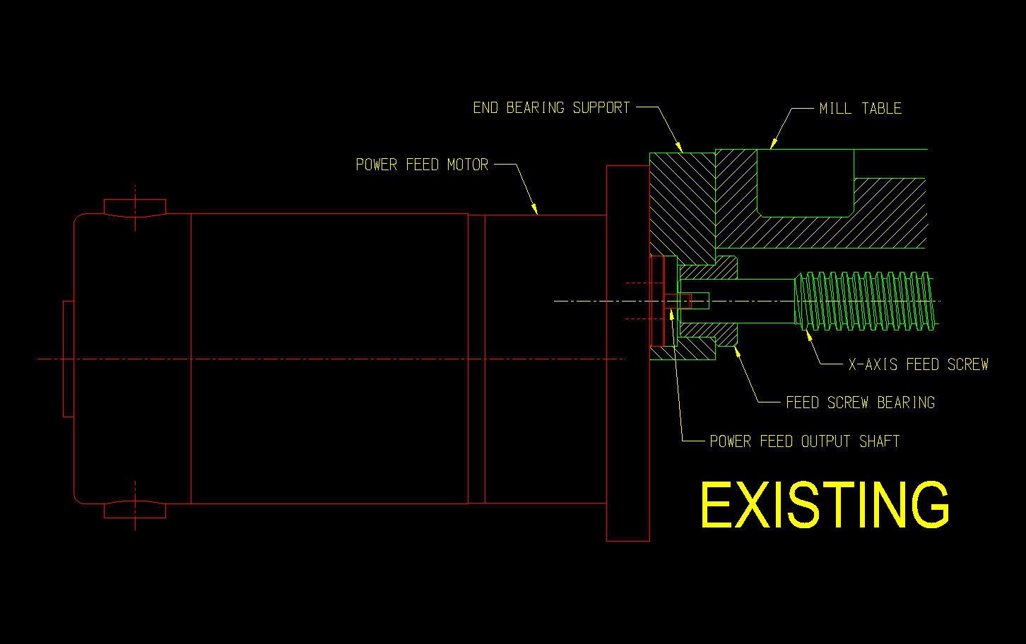
The output from the power feed unit is normally transferred to the longitudinal feed screw by means of a blade coupler. The blade on the power feeds output shaft engages a corresponding slot in the end of the feed screw. Here is the basic layout (click for a larger view):
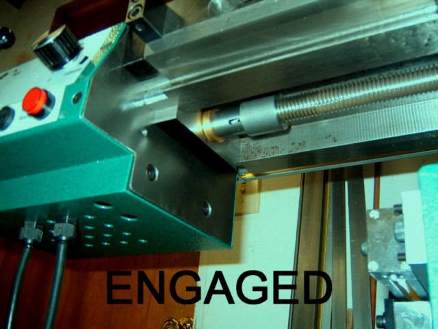
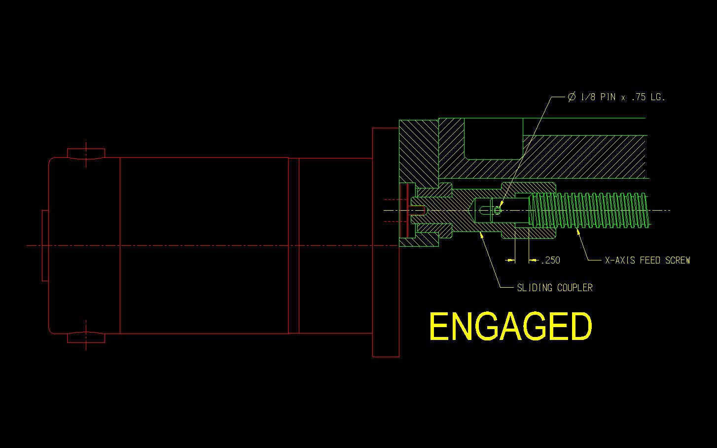
The method I came up with involves modifying the end of the existing feed screw, and introducing a sliding coupler between the feed screw and the output shaft of the power feed unit. The sliding coupler itself is coupled to the feed screw by means of a roll pin and slot arrangement. Alignment of the feed screw with the slotted end of the coupler is maintained with accurate sliding fits between the coupler I.D. and feed screw O.D. Here is the sliding coupler arrangement, shown in the engaged position (click for a larger view):
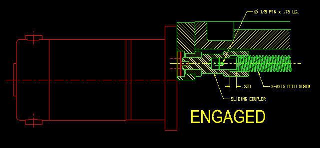
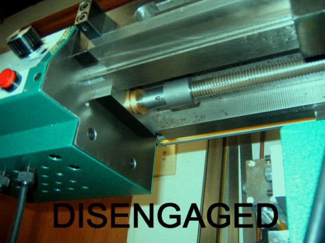
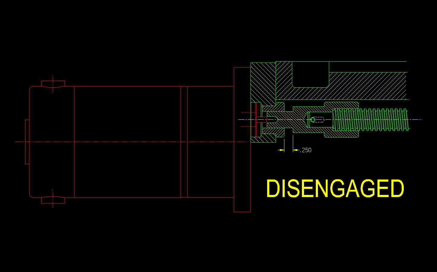
Note that the coupler is designed to operate with a .25 axial movement between the engaged and disengaged positions. Here is a view of the arrangement, shown in the disengaged position (click for a larger view):

A word to the wise: the dimensions shown on the drawings were derived from measurements I took from my machine, and should work fine for you, provided your mill is identical. However, its entirely possible that routine production variations will require a slight deviation. I strongly urge you to remove your power feed unit, and check all the relative dimensions (output shaft protrusion, blade width, how far the feed screw end is recessed in the bearing, etc.) to verify the arrangement. Make a sketch or CAD drawing to confirm the exact amount that the feed screw must be shortened.
You will probably want to begin by making the coupler. I used a piece of 1 dia. mild steel (CRS) to make this part:
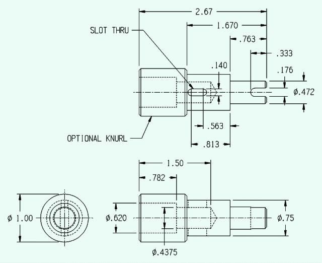
It is important that the three working diameters of this part (.620 & .4375 bores, and the .472 O.D.) be precisely concentric. The turned down portions (.75 & .472 dias) could be turned first, in the same setup, using a three-jaw chuck, but when the part is inverted to bore the opposite end, be sure to employ some accurate means for re-centering the part, such as a 4-jaw chuck or collet.
It would be a good idea to double-check the dimensions on your machine to verify the bore/O.D. dimensions. The .620 bore should give a thousandth or so clearance on the O.D. of your feed screw threads. Adjust the bore dimension as required to give a smooth running clearance (slip, but no slop). Likewise with the .472 dimension. Carefully check your feed screw bearing I.D. to verify the clearance requirement. As for the .4375 dimension, I used a 7/16 on-size reamer to size this hole (after boring to within a couple thousandths), but it is really only important that this hole be concentric with the .620 hole, as the feed screw shank can later be turned to give an accurate fit.
Note: Using a 7/16 reamer is also a good idea because it provides an easy way to clean out any burrs that remain after milling the .140 thru-slots.
The drawing shows an optional knurl on the 1 O.D. surface. I thought this might be very helpful for grasping the sliding coupler when I first conceived this project, and was intending to add one after my first trial fit of the coupler system, but it turned out to be completely unnecessary in actual use. If you enjoy knurling, go ahead and use it.
With the coupler finished, its time to remove the feed screw from the mill. I didnt have any problem with this, but you want to proceed carefully if you have not had your screw out before. There may be some slightly different configurations to the feed screw bearing/index collar/handwheel setup on various mills. Here is the parts diagram for my mill:
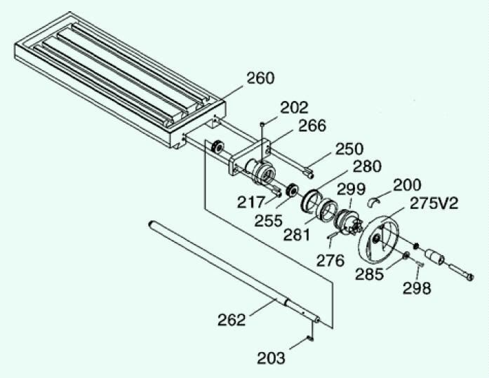
Removal of the #266 X-Axis Bearing Seat (the parts list incorrectly refers to this part as the Y-Axis Bearing Seat) might be slightly difficult. As a first step, I suggest removing the (2) 6MM screws (#217). Lock the table and use the handwheel to feed the table to the right. This should free up the bearing seat, perhaps with some light tapping from a brass hammer as well. With the bearing seat unseated from the table, but before removing the assembly from the machine, go ahead and remove the handwheel by removing screw #298. Then remove hub #299 by tapping out its taper pin (#276). Use caution at this point, as the ball bearings (#255) will be liberated from their housings. With the #299 hub removed, the #266 bearing seat can be removed the rest of the way. A slight prying action between the end of the table and the bearing seat might be needed here. With the bearing seat removed, the feed screw can be unscrewed from its nut and removed from the machine.
Note: the feed screw is not hardened (at least, mine wasnt) though it seems to be made of a good grade alloy steel, and machines quite nicely with HSS tools. I used a 4-jaw chuck to hold the screw for turning, with the long end passing back through the spindle.
The feed screw end is best machined in two steps. The first step is basically to establish a reference point 2.018 from the original end of the screw. Therefore, the .45 dia. dimension is not critical at all.
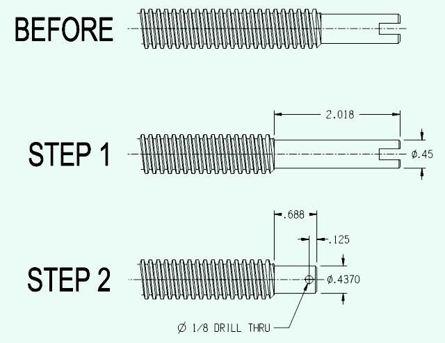
Following Step 1, the screw can be removed from the lathe for sawing off the excess length, or you can part it off in the lathe. Face the end of the cut-off screw accurately to the .688 dimension. The .4370 dia. should be a smooth running fit in the in the corresponding hole in the feed coupler.
Accurately locating and drilling the 1/8 hole in the end of the feed screw could pose a slight dilemma, since you would probably use your mill to do this -- which now lacks a longitudinal feed screw(!) If your mill has digital readouts, you are in luck, as you can still accurately position the table manually (tapping on the end of the table with a soft-faced hammer works wonders when you get close!) If you dont have digital readouts, you may have to use your ingenuity a bit more. A milling attachment in the lathe would be another alternative.
Before reassembling the mill, check the fit of the coupler on the modified feed screw. It should slide freely, but without any noticeable slop, or side clearance. Also, check to make sure that the 1/8 drilled hole lines up with the slot in the coupler. If everything looks good, lubricate all working surfaces (including the feed screw threads, if necessary), and go ahead and thread the feed screw back in the mill far enough that the coupler can be placed on the end of the screw. Now proceed to thread the screw the rest of the way home, making sure to guide the end of the coupler as needed, so that it seats in the left-end feed screw bearing.
Reassemble the components at the handwheel end in the reverse order of disassembly (making sure that the bearings have ample grease). Now comes the moment of truth. Before driving the 1/8 x 3/4 split roll pin into place, move the sliding coupler back and forth to check for free movement. At the same time, look through the slot in the coupler to see if the 1/8 hole lines up with the ends of the slot at the extremes of the couplers movement. (In other words, verify the operation of the coupler as though the pin were in place, so that if you need to disassemble everything to make a slight modification, at least you wont need to drive the pin back out.) If everything looks good, go ahead and drive the pin into place. This will be an awkward exercise, at best, given the tight clearance and upside-down configuration.
Here is what the finished installation looks like on my mill, in both the engaged and disengaged positions:
Ive been using my mill with this setup for around six months now, and couldnt be happier with how it operates. Reaching under the table to shift the coupler one way or the other is much simpler than you would think. To engage the coupler, just push it to the left while turning the handwheel slowly. To disengage, push the coupler to the right, with the power feed turned off. I originally thought that some kind of detent mechanism might be necessary to hold the coupler in the engaged and disengaged positions, but this has turned out not to be the case. Good luck!
Paula
EDIT: After originally posting this, I heard back from one individual who implemented this mod. Although it all worked out well, he wound up having to change two dimensions on the coupler to fit his particular machine. Therefore, make sure to check all dimensions with your own mill before commencing machining, as apparently the manufacturing tolerances vary quite a bit more on these machines (especially the PF unit) than I would have thought.
To overcome this disadvantage, I installed a clutch (of sorts) between the x-axis feed screw of my G0619 mill and the power feed unit. Thus, when I want to move the table manually, the power feed unit is simply uncoupled from the feed screw. Since completing this modification, several others have expressed a desire to equip their mills with such a device. To that end, I offer the following drawings and pictures that I used in modifying my own mill. While not the most simple undertaking, neither is it particularly difficult, requiring only modest machining skills, access to a lathe (ideally, one that will pass a 5/8 diameter rod through the spindle) and a willingness to make a slight modification to your mill. Probably not the ideal project for the rank beginner, but if you have some machining experience, and have a good mechanical aptitude, you shouldnt have any problems.
The output from the power feed unit is normally transferred to the longitudinal feed screw by means of a blade coupler. The blade on the power feeds output shaft engages a corresponding slot in the end of the feed screw. Here is the basic layout (click for a larger view):
The method I came up with involves modifying the end of the existing feed screw, and introducing a sliding coupler between the feed screw and the output shaft of the power feed unit. The sliding coupler itself is coupled to the feed screw by means of a roll pin and slot arrangement. Alignment of the feed screw with the slotted end of the coupler is maintained with accurate sliding fits between the coupler I.D. and feed screw O.D. Here is the sliding coupler arrangement, shown in the engaged position (click for a larger view):
Note that the coupler is designed to operate with a .25 axial movement between the engaged and disengaged positions. Here is a view of the arrangement, shown in the disengaged position (click for a larger view):
A word to the wise: the dimensions shown on the drawings were derived from measurements I took from my machine, and should work fine for you, provided your mill is identical. However, its entirely possible that routine production variations will require a slight deviation. I strongly urge you to remove your power feed unit, and check all the relative dimensions (output shaft protrusion, blade width, how far the feed screw end is recessed in the bearing, etc.) to verify the arrangement. Make a sketch or CAD drawing to confirm the exact amount that the feed screw must be shortened.
You will probably want to begin by making the coupler. I used a piece of 1 dia. mild steel (CRS) to make this part:
It is important that the three working diameters of this part (.620 & .4375 bores, and the .472 O.D.) be precisely concentric. The turned down portions (.75 & .472 dias) could be turned first, in the same setup, using a three-jaw chuck, but when the part is inverted to bore the opposite end, be sure to employ some accurate means for re-centering the part, such as a 4-jaw chuck or collet.
It would be a good idea to double-check the dimensions on your machine to verify the bore/O.D. dimensions. The .620 bore should give a thousandth or so clearance on the O.D. of your feed screw threads. Adjust the bore dimension as required to give a smooth running clearance (slip, but no slop). Likewise with the .472 dimension. Carefully check your feed screw bearing I.D. to verify the clearance requirement. As for the .4375 dimension, I used a 7/16 on-size reamer to size this hole (after boring to within a couple thousandths), but it is really only important that this hole be concentric with the .620 hole, as the feed screw shank can later be turned to give an accurate fit.
Note: Using a 7/16 reamer is also a good idea because it provides an easy way to clean out any burrs that remain after milling the .140 thru-slots.
The drawing shows an optional knurl on the 1 O.D. surface. I thought this might be very helpful for grasping the sliding coupler when I first conceived this project, and was intending to add one after my first trial fit of the coupler system, but it turned out to be completely unnecessary in actual use. If you enjoy knurling, go ahead and use it.
With the coupler finished, its time to remove the feed screw from the mill. I didnt have any problem with this, but you want to proceed carefully if you have not had your screw out before. There may be some slightly different configurations to the feed screw bearing/index collar/handwheel setup on various mills. Here is the parts diagram for my mill:
Removal of the #266 X-Axis Bearing Seat (the parts list incorrectly refers to this part as the Y-Axis Bearing Seat) might be slightly difficult. As a first step, I suggest removing the (2) 6MM screws (#217). Lock the table and use the handwheel to feed the table to the right. This should free up the bearing seat, perhaps with some light tapping from a brass hammer as well. With the bearing seat unseated from the table, but before removing the assembly from the machine, go ahead and remove the handwheel by removing screw #298. Then remove hub #299 by tapping out its taper pin (#276). Use caution at this point, as the ball bearings (#255) will be liberated from their housings. With the #299 hub removed, the #266 bearing seat can be removed the rest of the way. A slight prying action between the end of the table and the bearing seat might be needed here. With the bearing seat removed, the feed screw can be unscrewed from its nut and removed from the machine.
Note: the feed screw is not hardened (at least, mine wasnt) though it seems to be made of a good grade alloy steel, and machines quite nicely with HSS tools. I used a 4-jaw chuck to hold the screw for turning, with the long end passing back through the spindle.
The feed screw end is best machined in two steps. The first step is basically to establish a reference point 2.018 from the original end of the screw. Therefore, the .45 dia. dimension is not critical at all.
Following Step 1, the screw can be removed from the lathe for sawing off the excess length, or you can part it off in the lathe. Face the end of the cut-off screw accurately to the .688 dimension. The .4370 dia. should be a smooth running fit in the in the corresponding hole in the feed coupler.
Accurately locating and drilling the 1/8 hole in the end of the feed screw could pose a slight dilemma, since you would probably use your mill to do this -- which now lacks a longitudinal feed screw(!) If your mill has digital readouts, you are in luck, as you can still accurately position the table manually (tapping on the end of the table with a soft-faced hammer works wonders when you get close!) If you dont have digital readouts, you may have to use your ingenuity a bit more. A milling attachment in the lathe would be another alternative.
Before reassembling the mill, check the fit of the coupler on the modified feed screw. It should slide freely, but without any noticeable slop, or side clearance. Also, check to make sure that the 1/8 drilled hole lines up with the slot in the coupler. If everything looks good, lubricate all working surfaces (including the feed screw threads, if necessary), and go ahead and thread the feed screw back in the mill far enough that the coupler can be placed on the end of the screw. Now proceed to thread the screw the rest of the way home, making sure to guide the end of the coupler as needed, so that it seats in the left-end feed screw bearing.
Reassemble the components at the handwheel end in the reverse order of disassembly (making sure that the bearings have ample grease). Now comes the moment of truth. Before driving the 1/8 x 3/4 split roll pin into place, move the sliding coupler back and forth to check for free movement. At the same time, look through the slot in the coupler to see if the 1/8 hole lines up with the ends of the slot at the extremes of the couplers movement. (In other words, verify the operation of the coupler as though the pin were in place, so that if you need to disassemble everything to make a slight modification, at least you wont need to drive the pin back out.) If everything looks good, go ahead and drive the pin into place. This will be an awkward exercise, at best, given the tight clearance and upside-down configuration.
Here is what the finished installation looks like on my mill, in both the engaged and disengaged positions:
Ive been using my mill with this setup for around six months now, and couldnt be happier with how it operates. Reaching under the table to shift the coupler one way or the other is much simpler than you would think. To engage the coupler, just push it to the left while turning the handwheel slowly. To disengage, push the coupler to the right, with the power feed turned off. I originally thought that some kind of detent mechanism might be necessary to hold the coupler in the engaged and disengaged positions, but this has turned out not to be the case. Good luck!
Paula
EDIT: After originally posting this, I heard back from one individual who implemented this mod. Although it all worked out well, he wound up having to change two dimensions on the coupler to fit his particular machine. Therefore, make sure to check all dimensions with your own mill before commencing machining, as apparently the manufacturing tolerances vary quite a bit more on these machines (especially the PF unit) than I would have thought.


