X2 Mill Overhaul - Advice welcome

Home Model Engine Machinist Forum

Help Support Home Model Engine Machinist Forum:

This site may earn a commission from merchant affiliate links, including eBay, Amazon, and others.
Hilmar,
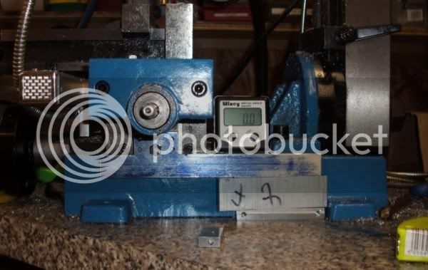
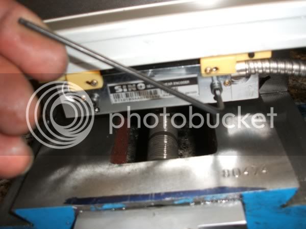
Thanks for pointing out that thread. I wish I'd seen that a couple weeks ago, now you have got me rethinking the mounting of my scales (this'll make round 3). I just used modified calipers as they were cheap.

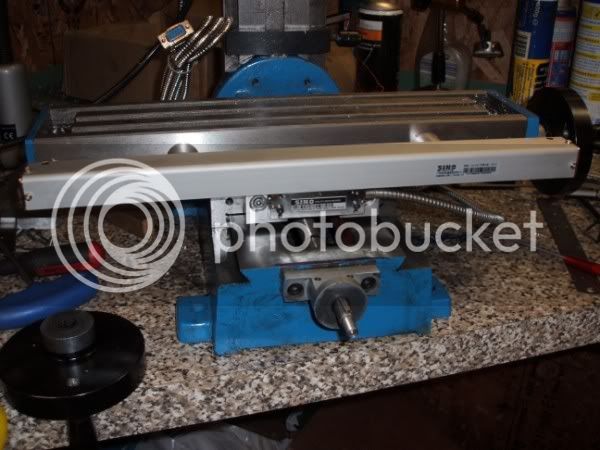
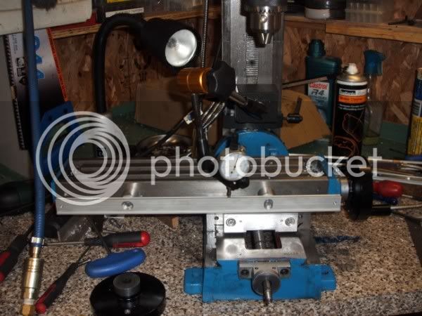
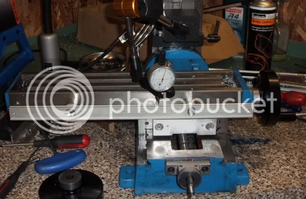
I'd originally mounted the X axis in the front, as FB did, then got a DRO display and moved the X to the back. It seems to collect more chips back there, however.


Dave,
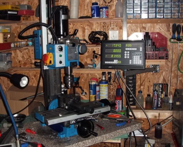
I like the DRO you bought. I think your kit is better quality and more accurate than the set-up I'm using with the cheap calipers. I don't fully trust the measurements it's displaying.

Keep us posted on the progress.
 
One thing I do, once in a while, seems to make at least some difference is shooting a small amount of powdered graphite (sold as lock lubricant) into the joints of the dove tails. It's non abrasive and adds a little lubrication which settles nicely into the small friction points. I've never seen it recommended anywhere, but it seems to work just fine here.

Ksouers
Dunno if it's applicable to your install, but most of us tend to think in terms of mounting things snug and tight to the frame. I took this to an extreme on my lathe by actually mounting the scale through the saddle in my first installation. It just seems like a natural way to do things. It also made the darned thing a really great swarf catcher.

When I purchased the new scales for my SX3 mill, I rethought the install a bit. I turned a pair of substantial columns from aluminum hex bar for mounts and moved the X scale away from the table (front) by almost 2 inches. I then made a modification to the reader attachment bracket to compensate for the new location.. This greatly reduced the accumulation of swarf on the scale and the reader, made battery changes easy and nothing interferes adjusting the gibs. I also sheltered the Y reader beneath the table, preventing heavy chip accumulations as well. NOTE... this placement is rather tricky when using a power feeder.

Steve
 
I am going to add the air spring conversion to my X2 in the next couple of weeks before I start my CNC conversion on it. I just ordered the CNC plans have begun acquiring parts for the conversion.

I have seen some mods to the X2 done by HossMachine over at CNCzone.com that involve a little grinding to get some more x and y room. Think I am going to do them. I figure since the air spring conversion adds to the Z axis.... why not right?

Eric
 
Steve,
Thanks for the suggestions. Everything is mounted quite rigidly, there isn't any wiggle at all. I've reworked the mounting since the picture on my shop thread, the scale is now vertically at the back of the table. And it most definitely is a swarf magnet! I'm working on a cover for it today.

The Y axis is under the table and is not much of a concern though it does get some swarf. It'll be covered as well.

It's the scales themselves I don't trust. I haven't noticed any inaccuracies, per say. But it seems that when I turn the handwheels very slowly a few thou the display doesn't show any movement.

It's probably just my perception.
 
Brass_Machine said:
I have seen some mods to the X2 done by HossMachine

I've come accross that name, he does nice work IIRC, Eric have you got a link ;)

As for me .......... ??? ............... I've learned a lot this weekend ............ measure 3 times and cut once mainly :D ......... thought I already knew that but I need to get used to working to thou's not 1/8" 's :-X

I've grabbed an hour or two when I could and made some progress, followed by 3 steps backwards ...... but I will get there.

The Z axis scale is mounted, just need to fix the mounting plate for the reading head, originally I thought the Z axis would be the hardest ........... then again, two things I didn't consider originally, ie: which part mounted to what :wall: and the fact that a 170mm scale is actually 300mm long (63/4" x 12"), obviously the other two also longer.

X axis was going to go on the back of the table till I realised that would reduce the Y travel, now it's going on the front, spaced off 20mm (3/4") so I can get to the gib adjusters, once I make a short allen key that is

as for thy Y axis, the reader head needs to be mounted on the base of the mill, which has a 5o angle, plus it runs out 0.5mm over it's length, not an insurmountable problem, just that all these little snags take "time" unfortunately the time to sorting the problem ratio seems heavily weighted towards spare time :eek:


................... anyway ............. it's interesting ;) and enjoyable, work will progress when I get a bit more time ::)

Oh' while I'm here .......... smoothing out the rough edges on the X & Y gibs and dovetails has helped a bit, well worth the few hours it takes imho.

CC
 
Dave,

I see you have found the major drawback to these upmarket scales. They are a lot longer than they need to be, but there is no way they can be shortened. I need to find all my solutions fairly soon.

Didn't you buy the scale covers for them? To keep all the nasties out.

One of the main advantages of a DRO system is that you can forget about leadscrew backlash. It is all taken care of because you are taking the reading directly from the main moving bits. It can make you a bit lazy at times, instead of adjusting the backlash out, you just leave it until it gets too bad.

For your concertina swarf barrier, I would suggest a bit of thick Visqueen attached at both ends, it folds in large curves rather than sharp angles, plus with a couple of ali angle supports it can be made a lot wider.

John
 
Thanks John,

Yes I did get the covers and I think I'm about there with the mounting issues, no real problems, just a case of time and effort, plus "measuring" ;) ........... it's been an enjoyable weekend and I've learnt a lot, which is good. Once I get a little more free time X and Z should be up and running, and once the mill is operational I should be able to sort out Y ........... the little beggar :big:

Good tip about the visqueen, I'd been thinking about all sorts ....... even cling film ??? good to have a different perspective, should work just fine.

Cheers

Dave
 
Well, I've progressed a little

X & Z are now sorted and it seems to work, Y is next in line :D

DSCF3691.jpg


DSCF3685.jpg


DSCF3699.jpg


Then I'll have to battle with the instruction manual ............ I hope it's better than the instructions for the scales, I want to swap the cable position on the Y reader, so had a look in the manual .....

....... and I quote (word for word) ..............


"(2) M4 hexagram bolt into the adjust screw holt and please do this one by one for flab the cover board which has airproof bar at the top, when noticing the gap. Please pry the cover board along the top by the screwdriver.
(3) Loose two M3 "-" bolt of the moor cable, remove the cable and end. Exchange the favour.
(4) Before covering the cover board, you must clean the old airproof bar and wipe the new one, if you do not have the new one, you can use butter order to instead of that, but the effect is not so good, only in support."


I could go on but I can't see for the tears of laughter, needless to say I've filed that manual in a safe place ;D ............. I'll have a look at the cable after I've talked to the suppliers. (Who actually supply their own copy of installation instructions for the scales, and they are quite good, but it don't cover the cable swap) ................ YET ;)

CC
 
In fact Dave it is a rather simple operation.

All they are saying is, take the cover off by undoing all the securing screws, you might have to pry off using small screwdriver, undo the screws that secure the cable, and swap over end to end. Lubricate the seal before refitting cover.

Vellygudstructions, OKallnow.

Take the instructions for the readout gently and you will have no trouble. I powered mine up in the house with one scale fitted and played about for an hour. Had it cracked, dead easy. If I can do it, so can all the other village idiots.
I would also suggest you only go for the four decimal places rather than five (in imperial), otherwise you will be chasing your own a**e thinking things are going wrong, when the scales are moving due to vibration, and figures are jumping up and down on the display.

John
 
Bogstandard said:
In fact Dave it is a rather simple operation.

Vellygudstructions, OKallnow.

I understand it much better now John :D ::)

but ............... the phrase ...............

"Note: The tools use in taking down in each step is partnership, avoiding the screw head sleeking."


has me slightly baffled ???

;) CC
 
CrewCab said:
I've come accross that name, he does nice work IIRC, Eric have you got a link ;)

....
CC

HERE ya go. Meet the X2 CNC Freak. He has free plans up the on CNCing your X2 plus a couple of other mods. Namely the x & y axes mods.

Eric
 
Well, a couple of old adage's spring to mind

Rod ........ and ......... for my own Back

One step forward ............ two back ............


etc, etc ::)


But progress has been made, not a lot, but still progress.

1) DRO Fitting ................. X & Z are complete and seem to work well, unfortunately I missed the fact that I cant refit the X axis table lock screw due to the position of the scale :wall: .............. as a temporary fix I've used an allen screw and I can get at it with my modified allen key, It'll do for now. I've come up with loads of complicated ideas for getting over this problem but the simplest which comes to mind is just fit it on the rear (there is room) and use a shaped brass plug between the screw and dovetail.

Y axis was just about complete (LH side) when I realised that if I fit a power drive I will loose a fair bit of travel, so "rethink time", now it's going on the RH side but different brackets are required to lower the scale below the gib's so once I obtain a bit more aluminium plate (good old ebay) .......... we will recommence ;D ....... lowering the scale means the lock for the Y axis will be accessible so one less hiccup there.

2) Binding at each end of the travel (X and Y) ....... having read a very long, but interesting thread on another forum (with a lot of very good advice from Mcgyver :bow: ) ........... I realise lapping is not the way to go, It seems I need to identify the high spots then deal with them accurately, I may be a while sorting this matter but I'll persevere ;)

CC
 
Dave,
How did the Y axis work out? And where are the pictures? ???
 
ksouers said:
Dave,
How did the Y axis work out? And where are the pictures? ???

Kev, Y axis turned out fine, finished it at the weekend.

Got to say I'm impressed with the whole kit, it certainly makes using the mill easier and backlash doesn't come into the equation any more. Anyway, briefly;

After a couple of false starts :D ........... all now works well, I decided (on all 3 axes) to make the scales "the moving part" and the reading head fixed. The Z axis was the easiest as the backing plate for the scale was just re drilled and bolted directly to the mill head, the reading head was mounted on an aluminium plate packed off the column (about 8mm). Both X & Y needed a plate to mount the scale on and X was packed out by 20mm to give access to the gib adjusters, Y was packed out about 6mm otherwise the mounting scale plate would have caught the column. The read heads need to be packed out about 8mm more than the scales which is fairly straightforward, apart from on the Y axis the base of the mill slopes about 5o and in addition the machined dovetail isn't quite parallel to the outside edge of the mill base; not a lot only about 1mm, but it needs taking into account.

So each scale / bracket was set up fairly closely with an angle gauge

DSCF3702.jpg


Then "fine tuned" to get as little run out as possible

DSCF3685-1.jpg


Brackets for the read heads fitted, these are temporarily held in place with plastic clips so it's a case of getting the head nicely lined up with it's bracket, (each one has 4 x jacking screws to help) then bolting it up and removing the clips.
DSCF3689.jpg


CC
 
I see yours was a bit more complicated John ............. and bigger scales :D

I've quite enjoyed mi'self, but in my case it's part of the leaning curve, from your point of view I can see it's just another obstacle to being fully operational, and of course, unlike me, you don't need practice in machining a bit of aluminium plate ;)

By the way, I've lost count of the number of times the little mill has been put back together during this project, it must be at least a dozen, ??? ............... my muscles were relieved it's the X2 and not the X3.

CC ;D
 
Not just another obstacle Dave, everything is a challenge to do the best you can. I spent more time thinking about it than actually doing any making. I did it by thinking from the finished result backwards. There is in fact only 1/8" clearance between the moving head and the standoffs I made for the kill switch bar and the same at the bottom of the head as it goes past the drip tray, so basically I only had a max of 1/4" to play with. If I had planned that wrong, it would have been a real problem job.

It wasn't machining either, more like hacking. Vice not square, no parallels, just did enough to make a neat job (on the bits you can see).

Over the years you will appreciate the number of times you have stripped it down, because if anything goes wrong, you could fix it in your sleep. There is nothing like knowing how your machine is built.

You will get there in the end, and you will be able to say you did it all yourself.

I must admit, these Sino readouts are a real quality job. There is only one better than these IMHO, and those cost about three times as much.

John
 
Nice write-up, CC. Thanks.

If those scales are anything near what the documentation says they are, you have a really nice kit there. I like that they are accurate to .0002" (.005mm?), and I think that's what confounds me about mine. The display only shows to the nearest thousandth. I'm used to measuring table movement with dial indicators and now I don't have that frame of reference where even the slightest table movement shows up, tweaking to just a fraction of a needle width. I'm glad that I went to a DRO, I just have to change my way of thinking when using it.

Nice bit of creative problem solving. Congratulations on a job done well.
 

Latest posts

Back
Top