


Sshire
Well-Known Member
- Joined
- Jun 29, 2011
- Messages
- 936
- Reaction score
- 259
A few weeks ago, I started building Elmer's Wobble Plate engine. The first run is here.
[ame]http://youtu.be/R_Ozg6j57X4[/ame]
A simple engine and (unless I get requests for the complete build log) the build is basically straightforward cutting, milling, drilling, tapping and turning.
The one part that is not so straightforward, is the wobble plate itself. After reading Elmer's description of the technique to machine and attach the plate at an angle on a collar I stopped.
This seemed fraught with potential problems. You are supposed to make the plate and then turn down the collar, and test fit the plate until it is small enough in diameter that the plate tilts
at an angle that will result in .125 movement of the valve lever. Elmer also suggests grabbing the plate with a pair of pliers to hold the angle while testing and while soldering.
There are a number of issues here. How much pressure to put on the pliers; chances of successfully soldering this while holding a pair of heat sucking pliers with welding gloves and a few others.
I'm sure that scores of these engines have been built successfully using Elmer's method, but there must be a better, more precise and repeatable method.
After thinking about this for a few days, I came up with a way to do it that might just work. A split collar, milled at the correct angle.
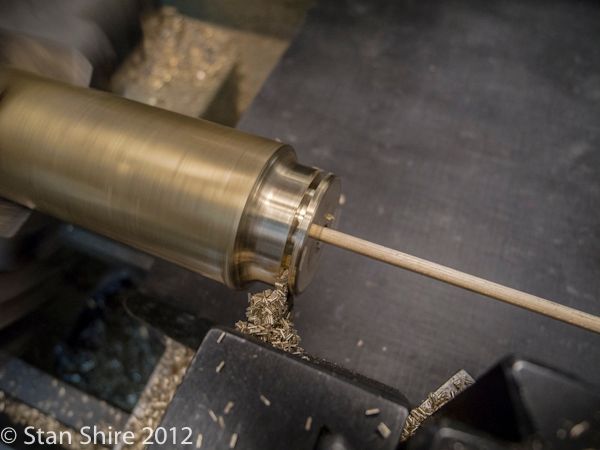
First step was to make the brass wobble plate. I also needed an excuse to try out the new Bison 3-jaw. Turned, drilled and reamed the center hole. This is the first deviation from Elmer's plans. Instead
of making the center hole @ collar diameter, I made it a bit larger than the shaft diameter to allow it to tilt. Turned the O.D. of the disk to 1" and parted off.
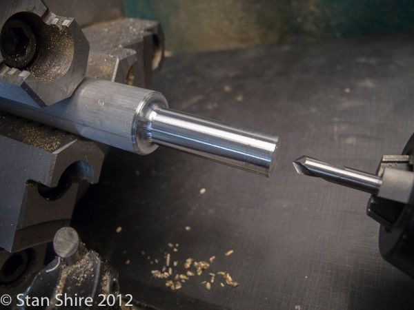
Next the collar. Drilled and reamed to the shaft diameter .
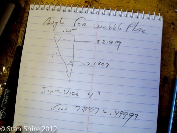
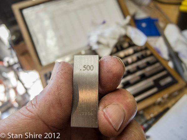
I planned to mill the angles with the sine vise so a few quick calculations here.
.49999 is close enough to this for me.
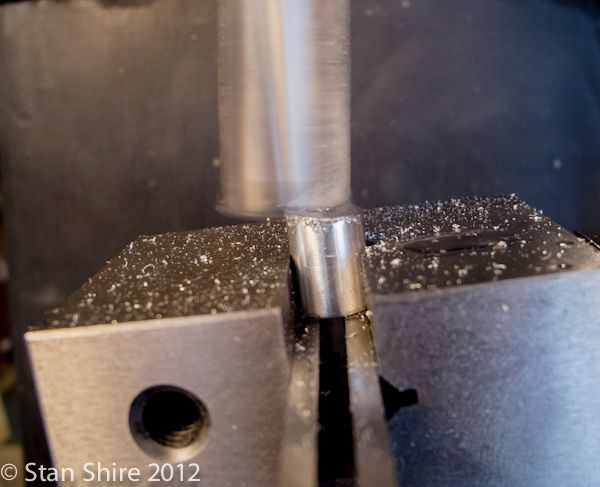
I cut the collar into 2 halves and milled each at the 7.1 degree angle.
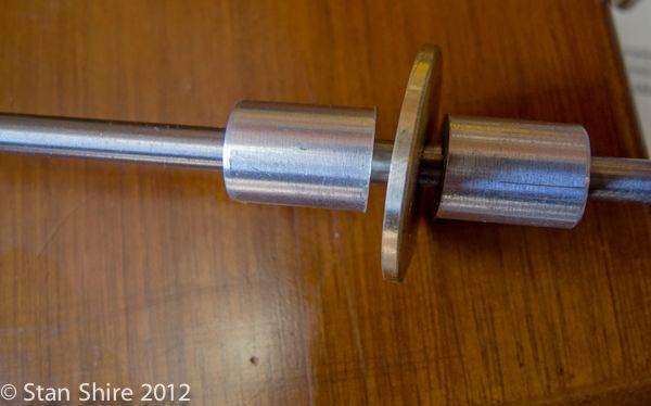
A bit of cleanup and the three parts look like this
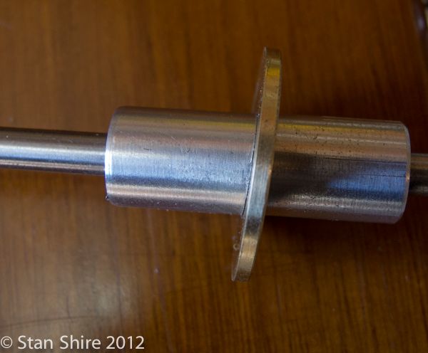
And like this pushed together
I had decided to bolt the three pieces together, so drilled and tapped a small piece of .75" 6061 rod as a jig and a 6-40 SHCS holds the assembly together.
Centered the whole group and set the bolt hole function on the DRO for 4 holes.
Drilled and tapped for 0-80 SHCS (only size that would fit around the collar.)
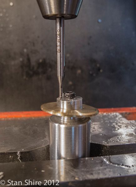
The completed wobble plate.
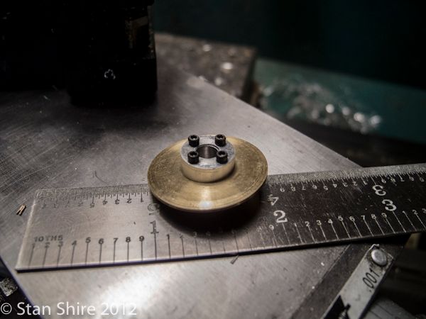
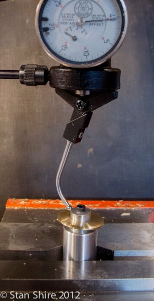
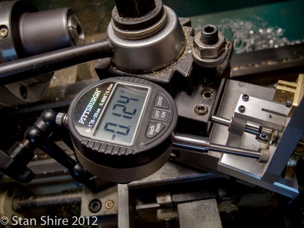
According to Elmer, the plate is supposed to have .125 deviation. Close enough.
[ame]http://youtu.be/R_Ozg6j57X4[/ame]
A simple engine and (unless I get requests for the complete build log) the build is basically straightforward cutting, milling, drilling, tapping and turning.
The one part that is not so straightforward, is the wobble plate itself. After reading Elmer's description of the technique to machine and attach the plate at an angle on a collar I stopped.
This seemed fraught with potential problems. You are supposed to make the plate and then turn down the collar, and test fit the plate until it is small enough in diameter that the plate tilts
at an angle that will result in .125 movement of the valve lever. Elmer also suggests grabbing the plate with a pair of pliers to hold the angle while testing and while soldering.
There are a number of issues here. How much pressure to put on the pliers; chances of successfully soldering this while holding a pair of heat sucking pliers with welding gloves and a few others.
I'm sure that scores of these engines have been built successfully using Elmer's method, but there must be a better, more precise and repeatable method.
After thinking about this for a few days, I came up with a way to do it that might just work. A split collar, milled at the correct angle.
First step was to make the brass wobble plate. I also needed an excuse to try out the new Bison 3-jaw. Turned, drilled and reamed the center hole. This is the first deviation from Elmer's plans. Instead
of making the center hole @ collar diameter, I made it a bit larger than the shaft diameter to allow it to tilt. Turned the O.D. of the disk to 1" and parted off.
Next the collar. Drilled and reamed to the shaft diameter .
I planned to mill the angles with the sine vise so a few quick calculations here.
.49999 is close enough to this for me.
I cut the collar into 2 halves and milled each at the 7.1 degree angle.
A bit of cleanup and the three parts look like this
And like this pushed together
I had decided to bolt the three pieces together, so drilled and tapped a small piece of .75" 6061 rod as a jig and a 6-40 SHCS holds the assembly together.
Centered the whole group and set the bolt hole function on the DRO for 4 holes.
Drilled and tapped for 0-80 SHCS (only size that would fit around the collar.)
The completed wobble plate.
According to Elmer, the plate is supposed to have .125 deviation. Close enough.
