What is a Westbury orbital valve?

Home Model Engine Machinist Forum

Help Support Home Model Engine Machinist Forum:

This site may earn a commission from merchant affiliate links, including eBay, Amazon, and others.

Anatol

Well-Known Member
Joined
Jan 21, 2018
Messages
313
Reaction score
56
Location
Los Angeles
I've reviewed with admiration and interest the thread :
Three Cylinder Radial Steam Engine
Discussion in 'A Work In Progress' started by SBWHART, Dec 14, 2009.
I'm a fan of Westbury's designs and of radials, and I am interested in (viable) non-reciprocating valves.

Could someone please explain the operation of the orbital valve in the Cygnet (or was the orbital valve in this project derived from the Elmer radial?)
Thanks anyone who replies.
 
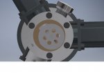
A while back I drew up plans in Autodesk inventor. Its a clever design. The steam or compressed air comes in via the centre rear port into the centre cavity of the orbital valve. As the valve rotates the cylinder inlet ports are uncovered and the steam is fed via these ports to the cylinder. After the cylinder has moved down the exhaust ports are uncovered allowing the exhausted steam into the area on the outside of the valve. It is then forced out via the port on top of the steam chest. The ports on the back of the engine contain both the inlet and exhaust port, being separated by the casting.

Are you going to build one?

Cheers
Greg
 
Hi Anatol,
The picture shown on the Hemingway site is actually the one I built from their castings many years ago.

http://www.hemingwaykits.com/acatalog/The_Cygnet_Royal___Edgar_T_Westbury.html

Stew, who only lives around the corner from me came and had a look at my engine and plans before making his own.

As it stands, the engine is a hi speed job, and so is a steam guzzler and only runs in one direction.

But with a little work, can be made to run in both directions by fitting a control valve onto it so that it swaps the way steam is fed into the engine, and while I was at it, I made it a speed control as well.

cygnet 1.jpg


cygnet 2.jpg


cygnet 3.jpg


I hope this helps a little

John
 
A while back I drew up plans in Autodesk inventor. Its a clever design. The steam or compressed air comes in via the centre rear port into the centre cavity of the orbital valve. As the valve rotates the cylinder inlet ports are uncovered and the steam is fed via these ports to the cylinder. After the cylinder has moved down the exhaust ports are uncovered allowing the exhausted steam into the area on the outside of the valve. It is then forced out via the port on top of the steam chest. The ports on the back of the engine contain both the inlet and exhaust port, being separated by the casting.

Are you going to build one?

Cheers
Greg

Greg
thanks for you reply and explanation. I'm having trouble imagining it from you description. A picture would be worth 1000 words in the case ;) ... But there only a few ways this can work. As I understand it, or imagine it, the valve is a rotating disc on the crankshaft. Steam was let in to an orbital passage curt on one side, close to the crankshaft, with a port which coincides with inlet ports on cylinder ports as it rotates.
Exhaust is similar, with an orbital passage outside there inlet passage. - or is exhaust unaflow style? I forgot.

"Are you going to build one?"

oh yes, along with all the others ...
seriously though, the 3 cyl high speed radial is a design is pleasing idea. And I'm become a fan of Westbury's work in general. But, I'd think very carefully about the kinds of criticisms of the original and (ie Stew's) improvements.
 
Hi Anatol,
The picture shown on the Hemingway site is actually the one I built from their castings many years ago.
As it stands, the engine is a hi speed job, and so is a steam guzzler and only runs in one direction.
John

Hi John,
thanks for your reply. I'd seen you engine on the Hemingway site. I'm not so concerned right now about one direction. But steam guzzling is an issue. Could you explain a little more ? Its the valve design inefficient, or is it just that it exhausts hot, only partially expanded, steam? How could you make it more efficient? By increasing the bore or stroke? (guessing here). Or reducing steam flow? (This is what your speed control did, right? )

It sounds like high speed engines are inherently inefficient? Those high speed engines are mostly, I think, unaflow, which I understood to be efficient.

If one was going for efficiency - maximum work output from minimum steam input - what designs are recommended?
 
This engine was desgned by Westbury to use a flash steam boiler to actually compete with the two stroke engines of the time, so anything above 80psi (and that has to be continual, so a flash steam boiler had to be used) could be used. I think it is a little like a turbine (which I have also built) where steam that isn't used just gets wasted away as I don't think that with the speed it can achieve, the steam just wouldn't have time to expand and work as efficiently as it should, like you say 'HOT'.
I did a few design mods to see if it could be easily made to reverse, but even though you could make it change direction (it was all to do with a take off from the main crank and it's position with regards to the crank centreline. I made two, one each with the offset either side, so could have it running in whatever direction I wanted but it meant a strip down each time. But having said that, either direction could be achieved, all it meant was swapping over the two steam ports. It ran slightly better in the correct direction when the correct rotation crank piece was installed.
The rotating valve at the rear, which controls the direction of the steam and exhaust HAS TO BE A PERFECT THICKNESS otherwise the entry steam can easily bleed into the exhaust line. It was a tricky job to get it to the correct thickness so very little bleed took place or you actually jammed up the rotating valve because your rotating valve got trapped because it was too thick, even a heavy hand in tightening could lock the control rotor area completely. I got mine to around two or three tenths gap and it ran very well. It took many hours of hand flatting to get the right thickness retaining parallelism of the rotor faces.

For efficiency and non loss of steam, you might have to pursue the way of poppet valves (like in a four stroke engine). I think it is that type that is normally
used with flash steam boilers. I don't think that normal slide valves could cope, whereas a poppet valve can open/close and seal instantly.

By searching on Youtube, you should find petrol fueled 4 stroke engines easily converted to steam.

BTW, my engine shown is the only engine I have ever sold (except for the ones I actually made commercially), if I remember rightly, it raised 400 pounds (about 600 bucks). All my other engines have been given away to friends and aquaintances around the world, if they showed a liking for one.

John
 
I'll post some Inventor views which could help. In my previous answer I got the in and outs the wrong way round, I'll correct that here.

Ports.jpg

This is a view of all three ports. The ports are oblong around the circle and have both inlet and exhaust in the same slot.

Rotary Valve.jpg

This is a view with the rotary valve in place.
Air or steam is fed into the side port of the steam valve and fills up the area outside of the rotary valve. The seals on both sides of the valve keeps the steam in the chamber where its supposed to be. Have a look at the position of valve and the upper port. the port is uncovered allowing the steam to be directed to into the inlet passage of that port

Ports2.jpg
Here at the the 3 o'clock position you can see the output port opening to the centre area of the valve which keeps the steam contained there until it exits via the rear port in the valve cover.
 

Attachments

  • Rotary Valve.jpg
    Rotary Valve.jpg
    36.7 KB · Views: 232
  • Ports2.jpg
    Ports2.jpg
    33.3 KB · Views: 263
  • Ports.jpg
    Ports.jpg
    76.9 KB · Views: 248
  • Ports2.jpg
    Ports2.jpg
    33.3 KB · Views: 225
  • Ports2.jpg
    Ports2.jpg
    33.3 KB · Views: 215
Thanks Greg
that is amazing, more complex than expected - over complex? So the disc is mounted eccentric? The holes open to cylinder inlet ports and the outer cavity opens to the sausage shaped exhaust ports?
I wondered about the six holes.
I wonder why he did't make it concentric with two 'tracks' and only one inlet hole and one outlet hole (180 deg opposite?) Is there a more subtle timing issue that makes the six holes necessary?

Regarding John's cautions about sealing, I am now wondering about a unaflow approach to a triradial. Maybe with poppets driven by a single cam.

BTW, in the Cygnet Royal, the cylinders are coplanar, I think. I wonder why he did not offset them slightly for big end clearance? Maybe it would complicate the valve mechanism?
 
I don't think you have got it yet Anatol.

In the drawing above the sausage shaped ports are the ports to the cylinders. The brown (brass?) port face is stationary.

The grey valve has a central recess front and back, leaving an annular working surface each side. The six holes are merely transfer passages to allow the exhaust steam to get from the inside port face of the valve to the outside exaust pipe in the centre of the cover plate.

Steam is admitted through a radial port in the outer wall of the valve chamber. As the valve wobbles on its eccentric pin its outside edge uncovers each sausage port in turn to let steam in, and at the same time the inside edge uncovers the ports on the opposite side to exhaust.
Its action is closely analogous to an ordinary slide valve.

The valve is free to rotate on its eccentric drive pin if wants to, just like the pad on an orbital sander.

The valve requires little force to drive it, as it is balanced: there is no steam pressure pressing it against the port face.
 
I think Charles has summed it up well. ETW came in for some criticism about the connecting rod design and placement, he may have modified it from a master/slave design. The comment was on the modelenginenews website. I can't find it again.
I didn't like the use of expensive and heavy castings, but I have seen builds from stock that use tubular ports to the heads. The one I saw was very neatly done.
Cheers
Greg
 
Last edited:
Back
Top